


2 • Hardware installation Model 6511RC User Manual
34 Matrix Switch hardware installation
Note
Missing cover plates can be replaced by calling Patton Sales at
+1 (301) 975-1000. The Sales Department is available Monday
through Friday, from 8:00 A.M. to 5:00 P.M. EST (8:00 to
17:00 UTC-5).
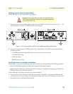
2. Inspect the rear of the chassis and verify that a cover plate is installed for each vacant module slot, and ver-
ify that each cover plate’s fasteners are tightened securely to the rear panel. Missing cover plates must be
replaced before installing the Matrix Switch.
Matrix Switch hardware installation
Do the following to install the Matrix Switch hardware:
1. Remove the Matrix Switch rear blade from its shipping container.
Note
Be sure to wear the anti-static strap to prevent electrostatic damage to
the blade.
Note
The Matrix Switch should be installed as close as possible to the ter-
mination jack provided by the Telco. The location should be well
ventilated. Do not block the rack chassis’ cooling vents.
2. Remove the slot cover plate, if present.
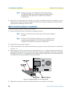
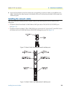
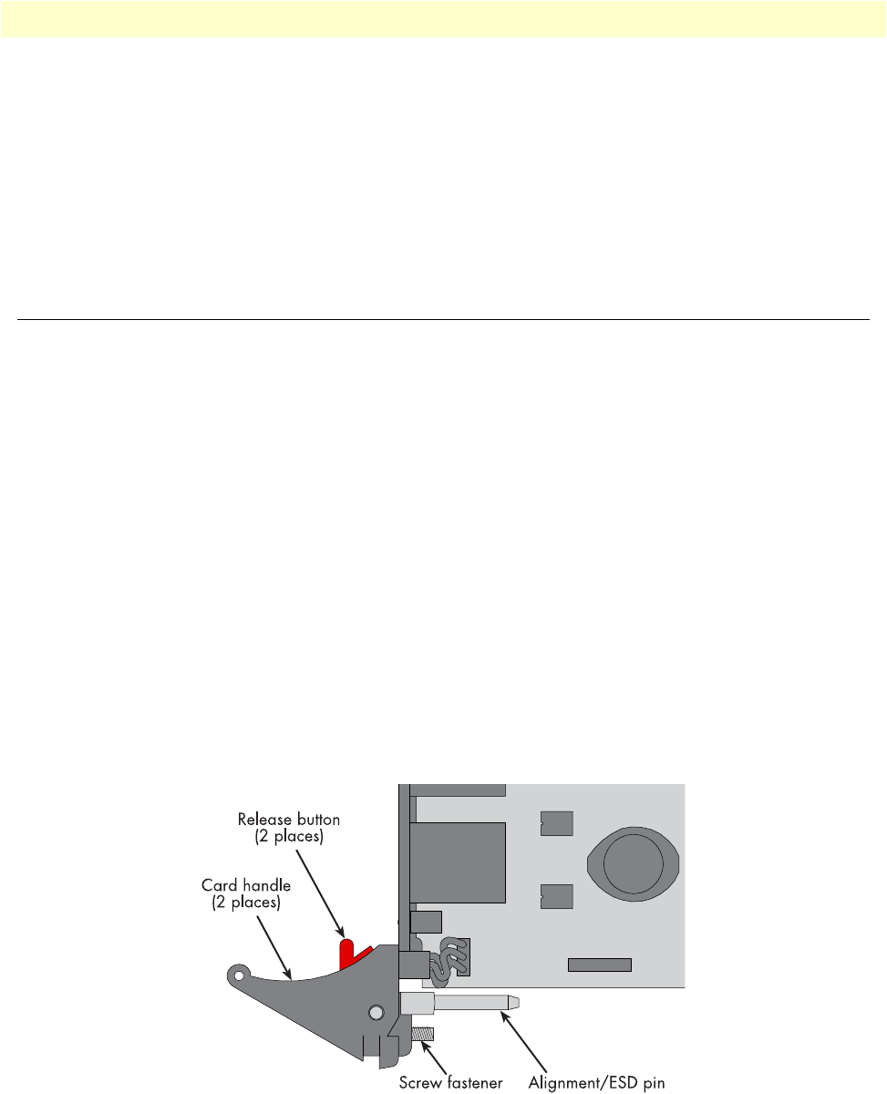
3. Unlatch both handles on the Matrix Switch blade by pressing in on the red release button in each handle
(see figure 12).
4. While holding the Matrix Switch from the card handles (see figure 12), align the Matrix Switch with the
guide rails of the appropriate slot and slide it back until it touches the backplane connectors and the align-
ment/ESD pin (see figure 12) engages the chassis. When the blade is fully seated, the red release buttons in
the handles click up automatically, thus locking the handles.
Figure 12. Alignment/ESD pin and card handle
5. Tighten the screw fastener located inside each handle to secure the blade to the chassis.