


5 • Troubleshooting and maintenance Model 6511RC User Manual
82 Introduction
Introduction
This chapter provides guidance to assist you when performing troubleshooting and fault analysis as a Matrix
Switch operator. Should you require more information or technical assistance, refer to chapter 6, “Contacting
Patton for assistance” on page 101.
Troubleshooting during initial deployment
The following table (see table 5) describes the symptoms for system faults that commonly occur when the
Matrix Switch is first deployed, along with suggested remedies for each fault.
Note
The symptoms listed in table 5 apply to single-fault scenarios involv-
ing the Model 6511RC. Performing the recommended corrective
action will solve such single points of failure, but may not correct any
additional faults that might co-exist. If you are unable to correct a
failure in your Matrix Switch, refer to chapter 6, “Contacting Patton
for assistance” on page 101.
Note
When removing the 6511RC from the chassis, follow the procedures
cited in section “De-activating the Model 6511RC” on page 80.
Note
When re-inserting the 6511RC into the chassis, please follow the pro-
cedures cited in chapter 2, “Hardware installation” on page 31
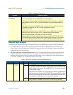
Table 5. Symptoms
Problem Corrective Action
POWER LED (green)
is extinguished
To verify that power is being supplied to the Model 6511RC via the CPCI chassis
power bus: verify that at least one chassis power supply module is installed in the
chassis and functioning normally.
POWER LED (green) is
flashing
The 6511RC has detected a power failure on a power bus. There may be a prob-
lem with the CPCI chassis power system which feeds the Model 6511RC such as a
failed power supply module in the chassis. The Model 6511RC will function nor-
mally with one power supply. Inspect the power supplies in the CPCI chassis to
identify and replace the failed power supply module. If no failed power supply is
found, or if the POWER LED continues flashing, contact Patton Technical Support to
determine if the Matrix Switch should be replaced.
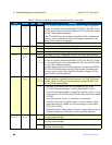
CPU FAIL LED (red) is lit CPU is unable to load the software from FLASH to RAM for operation. As soon as
possible, remove the Model 6511RC from the CPCI chassis, wait 30 seconds, then
re-insert the Model 6511RC into the CPCI chassis and see if the problem disap-
pears. If the CPU FAIL LED remains lit after the Model 6511RC completes the
power-up cycle, contact Patton Technical Support to determine if the Matrix Switch
needs to be replaced.
ALARM LED (yellow) is
lit or flashing
Indicates The 6511RC has detected a minor or major alarm condition. Examine
the Alarm System Overview web management page to determine exactly which
alarm(s) is(are) active.