


Verifying that the ForeFront chassis is properly installed 33
Model 6511RC User Manual 2 • Hardware installation
Verfying correct electrical grounding
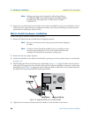
Do the following to verify correct electrical grounding:
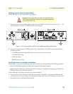
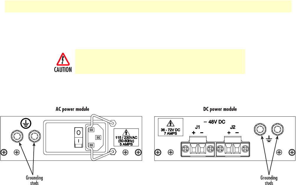
1. Inspect the rack chassis grounding studs on the AC power module or DC power module (see figure 11 for
studs locations) to ensure a #12 AWG ground wire is attached.
Figure 11. AC power module and DC power module grounding studs locations
2. Inspect the remote end the #10 AWG ground wire and verify that it is attached to one of the following
grounding sources:
– The building ground rod (generally located at the site’s main service entrance)
– A sprinkler system pipe
– A cold-water pipe
– Building structural steel
Verifying correct cover plate installation
Missing front or rear panel cover plates leave the chassis interior open and vulnerable to the following problems:
• Impaired EMI shielding against incoming and outgoing electromagnetic signals
• Reduced chassis cooling system efficiency, which can resulting in equipment overheating, especially in the
SHD laser subsystem on the Matrix Switch
Do the following to verify that cover plates are properly installed:
1. Inspect the front of the chassis and verify that a cover plate is installed for each vacant module slot, and
verify that each cover plate’s fasteners are tightened securely to the front panel. Missing cover plates must
be replaced before installing the Matrix Switch.
Improper chassis grounding may impair the operation of the
STM-1 electrical interface, thereby causing data transmission
errors on the STM-1 link.