3 • Configuring the Matrix Switch for operation Model 6511RC User Manual
56 Using a browser to complete Model 6511RC configuration
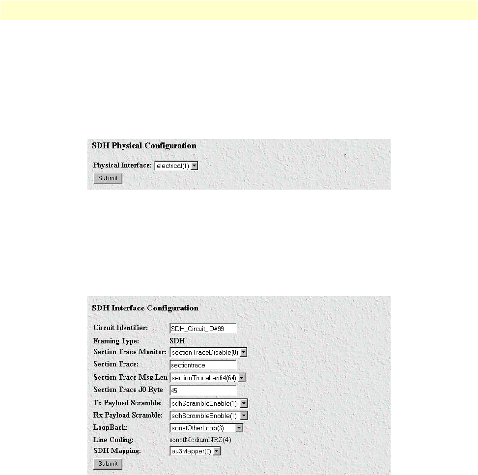
Configuring the SDH physical interface type
Do the following to define the physical interface type providing the STM-1 link:
1. In the SDH Physical Configuration section (see figure 38), select from the Physical Interface drop-down
menu the value that corresponds to the physical cabling attached to your STM-1 interface ports. If you are
using fiber-optic cable connected to the rear-card SC connectors, then select optical(0). If you are using
coaxial cables connected to the rear-card BNC connectors, then select electrical(1).
Figure 38. SDH Physical Configuration section
2. Click the
Submit
button to activate your selection.
Configuring the SDH interface parameters
1. In the SDH Interface Configuration section (see figure 39), for Circuit Identifier, enter an optional alphanu-
meric name for this STM-1 link.
Figure 39. SDH Interface Configuration section
2. If section trace is enabled in your connected SDH network, go to step 3. Otherwise, because section
trace is disabled, for the Section Trace Monitor parameter, select sectionTraceDisable(0) from the drop-
down menu, then go to step 7 to define the value of the SDH Payload Mapping parameter.
3. Because section trace is enabled in your connected SDH network, for the Section Trace Monitor parame-
ter, select sectionTraceEnable(1) from the drop-down menu.
4. For the Section Trace message string, enter the alphanumeric string your connected SDH network uses for
the section trace message string in the SDH frame.
Note
The Section Trace parameter only applies with 16-byte and 64-byte
section trace messages. For 1-byte trace messages, the J0 byte parame-


