


Matrix Switch test tools 87
Model 6511RC User Manual 5 • Troubleshooting and maintenance
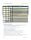
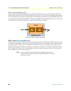
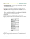
To understand how these test modes work, you must first understand the basic architecture of the Model
6511RC’s TDM mapping functions. The TDM mapping function provides the connection between the
STM-1 port and the H.110 bus. Within the TDM mapper (see figure 60) data passes between the SDH fram-
ing processor and the H.110 framing processor.
Figure 60. Matrix Switch TDM mapping architecture
The various loopback test modes route data through one or both of these framing processors, with the data
path making a U-turn in one framer or the other. Subsequent paragraphs describe the details of each loopback
test mode for the STM-1 port.
Facility Loop [sonetFacilityLoop(1)]
You can use the facility loop to test and troubleshoot the operation of the STM-1 link, including the Matrix
Switch’s STM-1 port and the fiber-optic or coaxial cables connected to it.
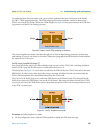
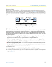
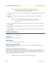
The facility loop (see figure 61) returns data received from the SDH facility (the STM-1 link) back to the same
SDH facility. In other words, when the Facility Loop is activated, the Matrix Switch receives data from the
STM-1 link and transmits the (unmodified) data back to the STM-1 link.
The U-turn for the facility loop occurs within the SDH framer on the Matrix Switch. The data path for the
facility loop traverses the SDH framer, but not the H.110 framer. Data enters the Matrix Switch at the STM-1
receive port, and enters the SDH framer where it loops back toward the STM-1 link, leaving the Matrix switch
at the STM-1 transmit port.
Figure 61. Facility Loopback test mode
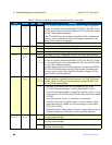
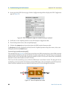
To activate the facility loopback test mode:
1. On the configuration menu, click the SDH hyperlink to display the SDH Overview page.
TDM Mapper
H.110 bus STM-1 port
Model 6511RC Matrix Switch
Rx
Tx
Tx
Rx
H.110
Framer
SDH
Framer