


3 • Configuring the Matrix Switch for operation Model 6511RC User Manual
54 Using a browser to complete Model 6511RC configuration
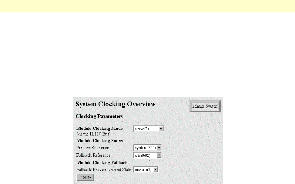
Example 2. For this example, another Matrix Switch is the chassis is the clocking master, providing the system
clock for the chassis, and your 6511RC is a slave. Your 6511RC will derive its timing from the H.110 bus sys-
tem clock as the main reference,
and from its STM-1 port as the fallback reference
.
To define the system clock-
ing parameters:
1. Connect a STM-1 WAN line to the 6511RC’s STM-1 port.
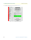
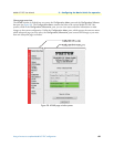
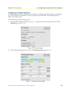
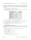
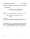
2. Click the System Clocking hyperlink on the 6511RC Configuration Menu (see figure 27 on page 48) to open
the System Clocking Overview page (see figure 35).
Figure 35. System Clocking Configuration page, example 2
3. For Module Clocking Mode, select slave(2) from the drop-down menu.
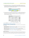
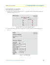
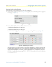
4. Under Module Clocking Source, for Primary Reference select system(600) from the drop-down menu.
5. For Fallback Reference select wan(602) from the drop-down menu.
6. Under Module Clocking Fallback, for Fallback Feature Desired State, select enable(1).
7. Click the Modify button.
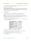
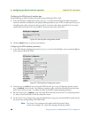
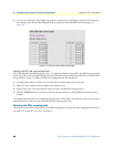
Configuring the SDH circuit parameters
In order for the STM-1 link to function correctly, you must correctly define the values of certain configurable
parameters that affect the SDH circuit. In order to configure the STM-1 link, you must first gather the follow-
ing information:
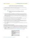
• Which E1 mapping path—either AU3 or AU4—will be used within the STM-1 link
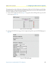
• Section trace message length
• The value of the JO byte for section trace messages
• Path-1 trace message length
• The value of the J1 byte for path-1 trace messages
• The value of path-1 signal label
• The E1 payload type, either asynchronous or byte synchronous