


2 • Hardware installation Model 6511RC User Manual
32 Introduction
Introduction
This chapter contains the following procedures for installing the Model 6511RC Matrix Switch:
Note
Before installing the Matrix Switch, you will need to obtain the line
type and encoding of the STM-1 link from your local telephone com-
pany (Telco).
• “Unpacking the Model 6511RC Matrix Switch”—lists the contents in the Matrix Switch shipping con-
tainer
• “Matrix Switch hardware installation”—describes installing the Matrix Switch on a flat surface or in a stan-
dard 19-inch rack
• “Installing the network cables” on page 35—describes installing the power and network interface cables
• “Completing the hardware installation” on page 40—describes testing the Matrix Switch hardware to verify
that it is ready for software configuration
Unpacking the Model 6511RC Matrix Switch
Inspect the shipping carton for external damage. Note any damage before removing the container contents.
Report equipment damage to the shipping carrier immediately for claim purposes. Save all packing materials in
case you need to return an item to the factory for servicing.
The Matrix Switch comes with the following items:
• The Model 6511RC Digital Cross-Connect (Matrix Switch)
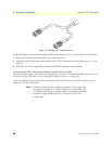
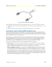
• One RJ45-to-RJ45 cable for use with the console and Ethernet ports
• A DB9-RJ45 (EIA-561) adapter for connecting a PC's serial port to the Matrix Switch console port
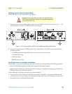
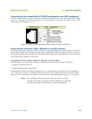
Verifying that the ForeFront chassis is properly installed
You must verify that the ForeFront chassis is correctly installed before installing the Matrix Switch hardware
into the chassis. Check for the following:
• Correct electrical grounding—Improper chassis grounding may impair proper operation of the STM-1
electrical interface, thereby causing data transmission errors on the STM-1 link. See section “Verfying cor-
rect electrical grounding” on page 33 for directions on verify chassis grounding.
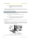
• Correctly installed front and rear panels over vacant chassis slots—Absent front or rear panels over vacant
module slots leaves the chassis interior open and thereby vulnerable to the following problems:
- Improper EMI shielding against both incoming and outgoing electromagnetic signals
- Impaired operation of the chassis cooling system, resulting in equipment overheating, including the SHD
laser subsystem on the Matrix Switch
See section “Verifying correct cover plate installation” on page 33 for directions on verifying proper cover
plate installation