


Using a browser to complete Model 6511RC configuration 71
Model 6511RC User Manual 3 • Configuring the Matrix Switch for operation
– tug2-6(6)
– tug2-7(7)
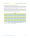
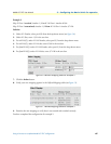
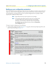
7. Each TUG-2 contains three TU-12s (which in turn contain one E1 each). To define the value of the TU-
12 parameter, select one of the following values from the drop-down menu:
– tu12-1(1)
– tu12-2(2)
– tu12-3(3)
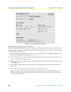
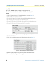
8. The three parameters you defined above specify a selected E1 signal stream within the STM-1 link. For E1
Slots, enter the timeslot numbers within the selected E1 link that you wish to map to the H.110 bus.
When entering E1 and H.110 timeslot numbers you must define the same number of timeslots on the
SDH and mid-plane sides of the mapping. The timeslots are defined by entering a text string that repre-
sents the timeslot numbers.
The following notation should be used for assigning timeslots:
– dash: (-), e.g., 1–4
– comma: (,), e.g., 1,4,9
– combo: 1-2,3,6-7
At this point you have defined the SDH channel composed of a selected E1 signal stream and a set of
timeslots within that E1. Now you must define the mid-plane channel to be correlated with the
SDH channel.
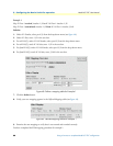
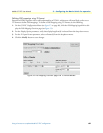
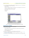
9. Under the heading Mid-plane Channel, in the first row, labeled to H110(5), for H.110 number, select your
desired H.110 port number from the drop-down menu.
10. In the first row, labeled toH110(5), for H.110 slots, enter the timeslot numbers you wish to map to the
H.110 bus (from the E1).
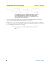
11. In the second row, labeled fromH110(6), select your desired H.110 port number from the drop-
down menu
12. In the second row, labeled fromH110(6), for H.110 slots, enter the timeslot numbers you wish to map
from the H.110 bus (to the E1).
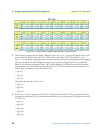
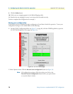
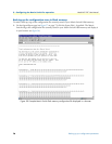
13. Click the Define button. The new mapping will appear at the bottom of the page in the Defined
Mappings table.
14. Examine the Defined Mappings table to verify that the new mapping appears and was correctly entered
and recorded.