


MGC Hardware and Installation Manual
4-33
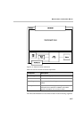
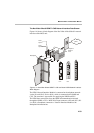
The Net-2/Net-4/Net-8 ISDN/T1-CAS Network Interface Data Stream
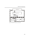
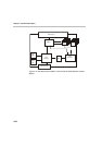
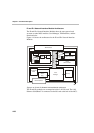
Figure 4-16 shows a block diagram of the Net-2/Net-4/Net-8/Net-8L network
interface of the MGC unit.
Figure 4-17: Net-2/Net-4/Net-8 ISDN/T1-CAS and Net-8L ISDN Network Interface
Block Diagram
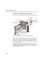
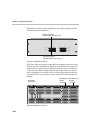
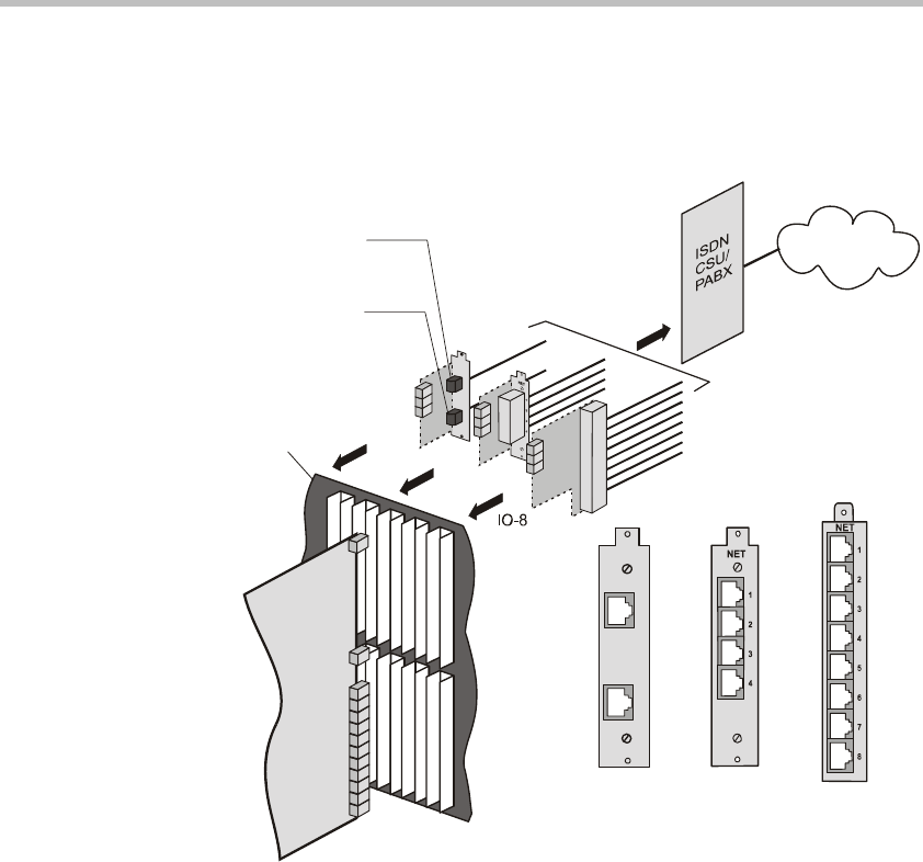
The ISDN Network Interface Module is connected to the telephone network
via the IO card (IO-2, IO-4 or IO-8), which is connected to the PABX and
CSU. The customer is responsible for supplying the PABX and CSU.
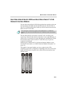
The ISDN data stream flows from the ISDN telecommunication network
through the PABX > CSU > MGC RJ-45 input connector > IO card (IO-2, IO-
4 or IO-8) > Backplane connectors > Network Interface Module to the
Backplane information bus.
Telephone
Network
Lines
RJ45
Span A
RJ45
Span B
Backplane
NET
A
B
IO-2
IO-4
ISDN
IO-2
IO-4
IO-8