


Chapter 4 - Hardware Description
4-6
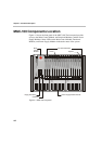
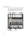
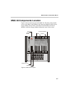
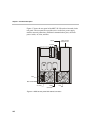
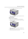
Figure 4-5 shows the top view of the inside of the MGC-100. The Main
Control Module, Functional Modules, and I/O cards are all connected to the
Backplane. The Power Supply Modules, located underneath the Main Control
Module and the Functional Modules, are connected to the Powerplane.
Figure 4-5: MGC-100 top (internal) view
Main Control
Module
Backplane
Function modules
FR
O
NT
R
E
A
R
I/O cards