


Chapter 4 - Hardware Description
4-8
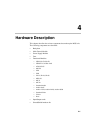
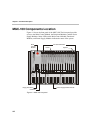
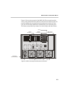
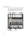
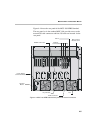
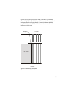
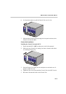
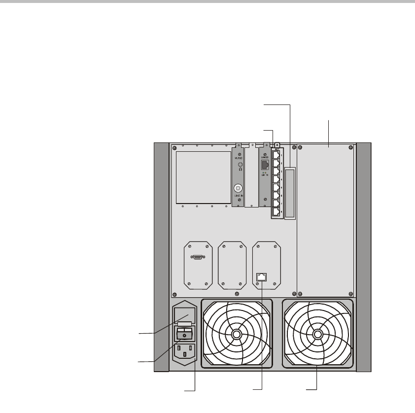
Figure 4-7 shows the rear panel of the MGC-50. I/O cards are inserted via the
rear panel. The rear panel also provides access to the fans, power supply
module, network connections, additional communications ports, the main
power switch, AC inlet, and fuse.
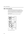
Figure 4-7: MGC-50 rear panel with external connector
AC Inlet
Main Switch
Fuse
IO Card
Slot A
Fan
RJ45
Connector
LAN
COM 1
Main Control
Module Cover