MGC Hardware and Installation Manual
4-7
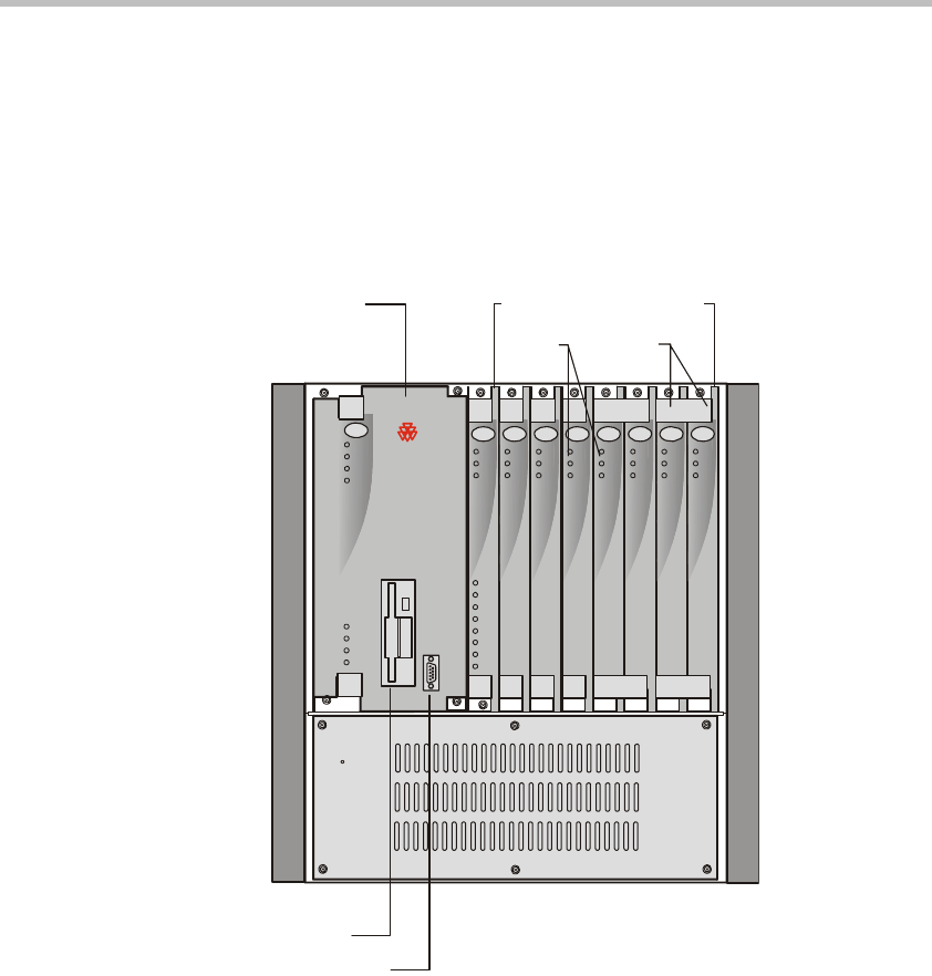
MGC-50 Components Location
Figure 4-6 shows the front panel of the MGC-50. The front panel provides
access to the Main Control Module, the Functional Modules, and the Power
Supply Module. Status LEDs on the Main Control Module, Functional
Modules, and Power Supply Module indicate the status of the system.
Figure 4-6: MGC-50 front panel
Ejectors
Floppy Disk Drive
Main
Control
Module
COM Port
Power
L1
L2
L3
Critical
Major
Minor
L0
CONT
MGC-50
PWR
OUT
Stby
Fail
Active
Functional Modules
Line 6
Line 7
Line 8
Line 3
Line 4
Line 5
Line 1
Line 2
StbyStby
FailFail
ActiveActive
StbyStbyStby
FailFailFail
ActiveActiveActive
Stby
Fail
Active
Stby
Fail
Active
VIDEOVIDEO VIDEOVIDEOAUDIOAUDIO
MG-323
PRI-8
LEDs
POLYCOM


