


MGC Hardware and Installation Manual
5-5
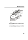
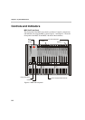
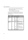
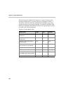
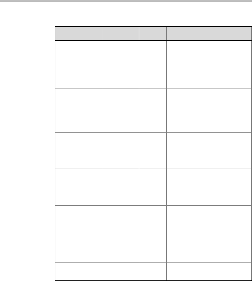
Functional
Modules
STBY
FAIL
ACTIVE
Green
Red
Yellow
On during normal operation
(refer to Table 5-2)
On when a failure has occurred
(refer to Table 5-2)
On when the module is handling
a conference (refer to Table 5-2)
Net-E1/Net-T1
ISDN, ATM and
H.323 Network
Interface Module
(additional
LEDs)
LINE A
LINE A
LINE B
LINE B
Yellow
Red
Yellow
Red
Span A yellow alarm (RAI)
Span A red alarm (LOS)
Span B yellow alarm
Span B red alarm
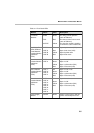
Net-2 Network
Interface Module
(additional
LEDs)
LINE 1/
LINE 2
Off
Green
Yellow
Red
Span x is not in use
Span x is OK
Span x yellow alarm (RAI)
Span x red alarm (LOS)
Net-4 Network
Interface Module
(additional
LEDs)
LINE 1/
LINE 2/
LINE 3/
LINE 4
Off
Green
Yellow
Red
Span x is not in use
Span x is OK
Span x yellow alarm (RAI)
Span x red alarm (LOS)
Net-8 Network
Interface Module
(additional
LEDs)
LINE 1/
LINE 2/
LINE 3/
LINE 4/
LINE 5/
LINE 6/
LINE 7/
LINE 8
Off
Green
Yellow
Red
Span x is not in use
Span x is OK
Span x yellow alarm (RAI)
Span x red alarm (LOS)
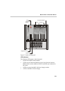
Power Supply
Module
IN/OUT Green Power-in from mains is OK. DC
power out to backplane is OK.
Table 5-1: Front Panel LEDs
Module Name Color Description