


Chapter 5 - System Maintenance
5-4
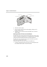
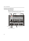
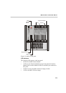
• 7 LEDs on Net-E1/Net-T1 ISDN Network Interface Module, Net-4
ISDN Network Interface Module, ATM Network Interface Module and
H.323 Network Interface Module
• 5 LEDs on NET-2 ISDN Network Interface Module
• 11 LEDs on NET-8 ISDN Network Interface Module
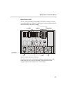
The system uses these LEDs to indicate operating states. The LEDs on the
Net-2/Net-4/Net-8 are tri-color. Depending on the states of the LEDs inputs,
the LED can be off, green, red or yellow. The LEDs on the front panel are
described in Table 5-1.
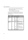
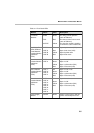
Table 5-1: Front Panel LEDs
Module Name Color Description
Main Control
Module (top
group)
CRITICAL
MAJOR
MINOR
L0
Red
Red
Yellow
Green
A critical fault is detected on the
MGC unit
A major fault exists on the MGC
unit
A minor fault exists on the MGC
unit
Reserved
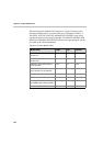
Main Control
Module (bottom
group)
POWER
L1
L2
L3
Green
Green
Green
Yellow/
orange
Power Supply is operating
normally.
Only one ISDN/T1-CAS Network
card is installed in the MCU, and
it is configured as the Primary
clock source. The LED is turned
off when no ISDN Network card
is installed.
A second ISDN/T1-CAS
Network module is installed and
configured as the backup clock
LED is active when the MCU is
restarted.