


Chapter 5 - System Maintenance
5-6
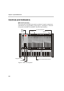
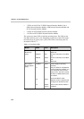
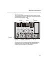
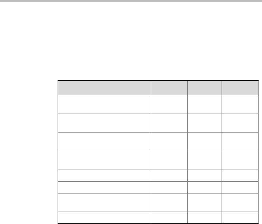
The three Functional Module LEDs function as a group. Each state of the
Functional Module and its associated LED array is described in Table 5-2.
The (IDLE, ACTIVE, FAILURE, and PARTIAL FAILURE) states are the
operational modes of the Functional Module. The (RESET, WAITING FOR
MCMS and LOADING SOFTWARE) indicates the stages during the startup
procedure of the Functional Module.
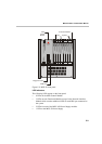
Figure 5-2: Function Module LEDs
Module State STBY FAIL ACTIVE
IDLE—Ready, but not used in a
conference
ON OFF OFF
ACTIVE—Used in one or more
conferences
ON OFF ON
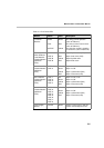
FAILURE—Error state; board is
out of operation
OFF ON OFF
PARTIAL FAILURE—Error state;
part of board is out of operation
ON Flashing ON/OFF
RESET—Board is in Reset state ON ON ON
TEST—Power-on self test OFF OFF Flashing
WAITING FOR MCMS—Waiting
for MCMS to start loading software
Flashing Flashing OFF
LOADING SOFTWARE ON Flashing OFF