


MGC Hardware and Installation Manual
3-5
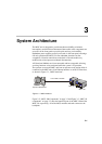
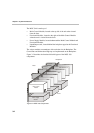
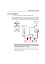
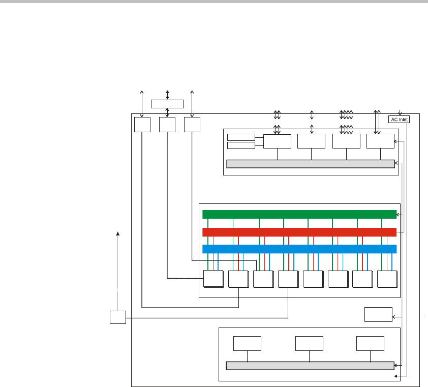
Figure 3-5 shows the physical layout of the MGC-100 and how it interfaces
with the outside world.
Figure 3-5: MGC-100 functional block diagram
RS232
RS232
Ethernet
Power
Module
Power
Module
Power
Module
Fan
Module
Audio
Module
Video
Module
Data
Module
Power Bus
Communication Bus
Information
Power Plane
Serial
Interface
Main
CPU
Comm.
Controller
LAN
Interface
CPU Bus
Floppy Disk
Hard Disk
LAN
A
larms
Workstations
Workstations 120/230 V
ISDN
Network
CSU/PABX
ATM
Network
H323
Network
Serial
equipment
I/O
Card
I/O
Card
I/O
Card
Main
Control
Module
Power
Supply
Unit
MGC-100
MUX
Module
MPI
Network
Interface
ATM
Network
Interface
H323
Network
Interface
ISDN
Network
Interface
MPI
Box
Functional
Modules