MGC Hardware and Installation Manual
5-3
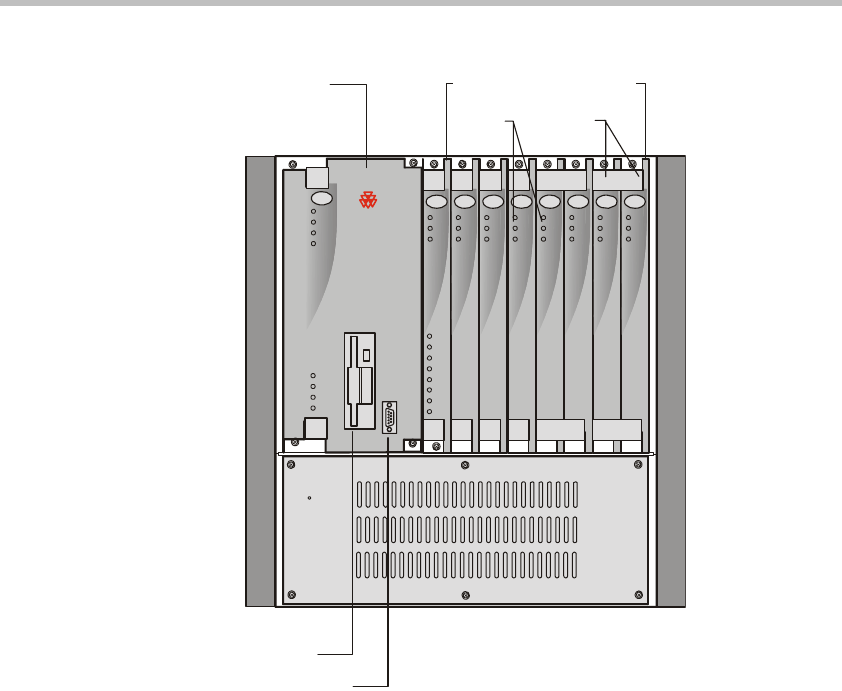
Figure 5-2: MGC-50 front panel
LED Indicators
The following LEDs appear on the front panel:
• 8 LEDs on the Main Control Module
• 3 LEDs on each Functional Module except for the Network Interface
Module which contains additional LED for each PRI span connected to
the system
• 2 LEDs for each of the MGC-100 Power Supply modules
• 1 LED on the MGC-50 Power Supply
Ejectors
Floppy Disk Drive
Main
Control
Module
COM Port
Power
L1
L2
L3
Critical
Major
Minor
L0
CONT
MGC-50
PWR
OUT
Stby
Fail
Active
Functional Modules
Line 6
Line 7
Line 8
Line 3
Line 4
Line 5
Line 1
Line 2
StbyStby
FailFail
ActiveActive
StbyStbyStby
FailFailFail
ActiveActiveActive
Stby
Fail
Active
Stby
Fail
Active
VIDEOVIDEO VIDEOVIDEOAUDIOAUDIO
MG-323
PRI-8
LEDs
POLYCOM


