


Chapter 2 - Hardware Installation
2-20
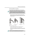
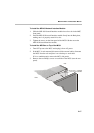
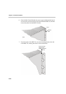
10. Connect the serial cable running from the DCE to the appropriate 37-pin
connector on the rear panel of the MPI Box. If dialing is used, connect
the appropriate cable from the DCE to the 25-pin connector on the rear
panel of the MPI Box.
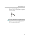
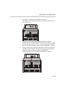
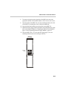
Whenever the MGC unit is used as a DCE and connected straight to an
endpoint the serial data stream flows from the endpoint (DTE) through
the serial connector to the MPI box. The connections stay the same,
meaning; the endpoint is connected to the back of the MPI box by way of
the 37-pin connector, and the other side of the MPI box is then connected
by way of the 160-pin connector to the MPI card in the MGC unit. For
more information, refer to Chapter 4, “The MPI-8 Network Interface
Module” on page 4-39.
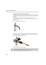
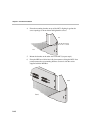
• If V.35 or RS-530 cable is used, attach the special adapter (provided with the
kit) to the 37-pin prior to connecting the serial cable from the DCE.
• The serial (MPI) network properties must be defined in the Network
Services, For details, see MGC Administrator’s Guide, Chapter 3.