


Chapter 2 - Hardware Installation
2-8
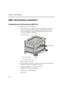
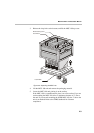
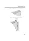
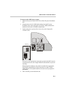
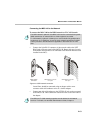
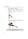
5. Carefully rotate the MGC-100 counterclockwise 90°, making sure the
Control Unit is at the bottom left.
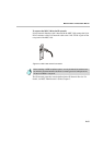
6. While supporting the MGC-100, place it on the 19” rack and screw the
brackets to the rack, securing it with the screws and nuts supplied with
the rack.
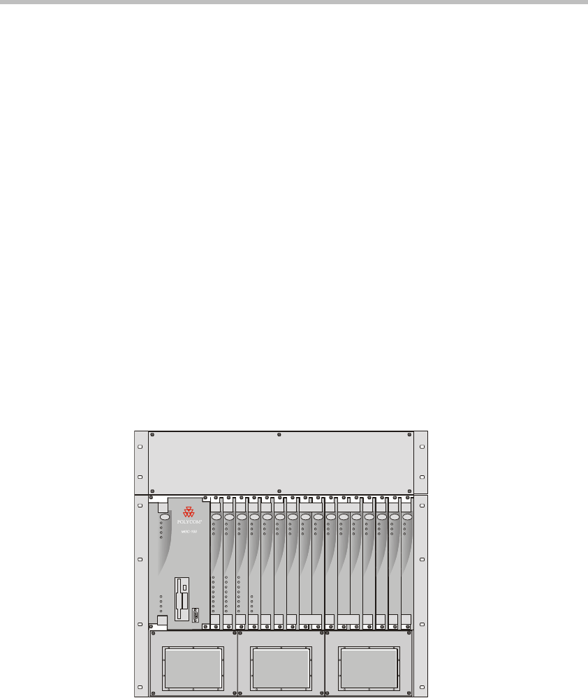
NEBS Standard
For installations based within the United States, an MGC-100 DC NEBS
compliant system is available. The NEBS compliant systems differs in its
construction of the frame and the power supply. All else remains the same.
The construction of the MGC-100 is 12 U’s, (1 U = 4.3 cm) which makes it
higher by 3 U’s than the original frame of the MGC-100. This design allows
for a cushion of air to be present, ensuring safety in case of a heat related
problem.
In addition, the power supply is also designed differently by allowing the
circulation of cool air, providing a safety tolerance in case of a heat related
problems.
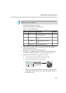
Use only shielded LAN cables where the shield is grounded at both ends
when connecting to the IO LAN port of the IP+48 on the MGC+ rear panel.
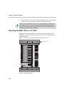
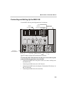
Figure 2-4: NEBS Standard Unit Front View
Power
L1
L2
L3
Critical
Major
Minor
L0
CON T
Line A
Line B
Stby
Fail
Active
Stb y
Fail
Active
Stby
Fail
Active
Stb y
Fail
Active
Stb y Stby
Fail Fa il
Active Act ive
Stb y
Fail
Active
Stb y Stby
Fail Fa il
Active Act ive
Stb y
Fail
Active
Stby Stby
Fail Fail
Active Active
Stby
Fail
Active
Stby
Fail
Active
Stb y
Fail
Active
NET-E1
MUX MUX DATA DATA VIDEO VIDEO VIDEO AUDIOVIDEO AUDIO
Stby
Fail
Active
AUDIOAUDIO
Line 6
Line 7
Line 8
Line 3
Line 4
Line 5
Line 1
Line 2
Line 6
Line 7
Line 8
Line 3
Line 4
Line 5
Line 1
Line 2
Line 6
Line 7
Line 8
Line 3
Line 4
Line 5
Line 1
Line 2
NET-8NET-8 NET-8