MGC Hardware and Installation Manual
2-9
Connecting and Setting Up the MGC-100
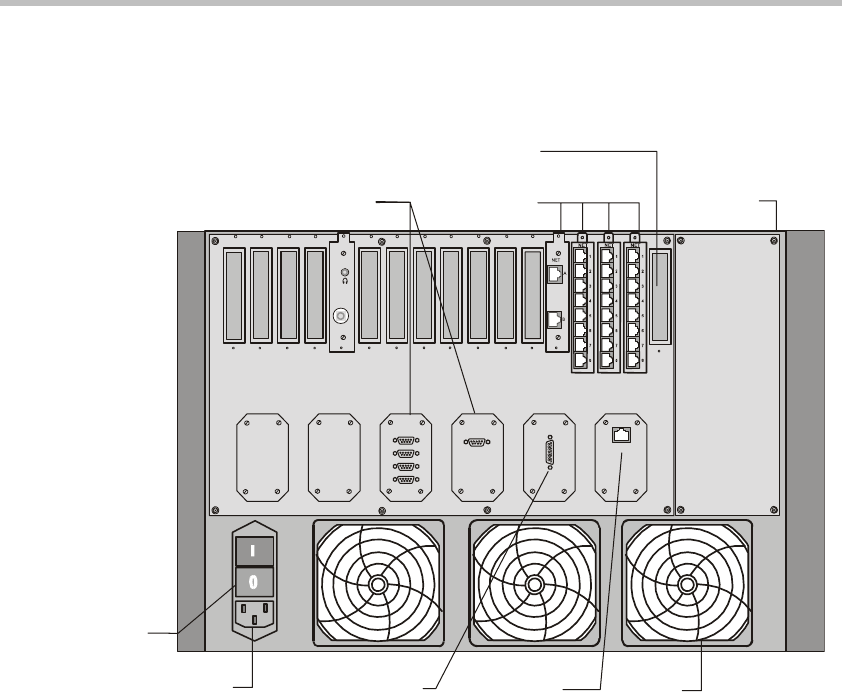
Use the MGC-100 rear panel diagram below for reference.
Figure 2-5: MGC-100 Rear Panel with External Connectors
To connect the MGC-100 to the network and power source and set up the
system the following procedures are performed:
• Connecting the MGC unit to the power source (AC inlet or -48DC power
distribution unit)
• Connecting the MGC unit to the LAN Network
• Connecting the MGC unit to the Operator Workstation (PC) directly via
RS-232 (optional)
• Connecting the MGC unit to the network(s)
LAN
ALARMSCOM 1
COM
MUSIC
LINE IN
AC Inlet
Main Switch
and Circuit Breaker
Main Control
Module Cover
Network
Connectors
RS232
Connectors
Fan
Dry Contacts RJ45 Connector
S
lot A
10/100 Mbits


