


MGC Hardware and Installation Manual
5-7
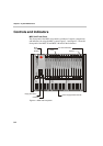
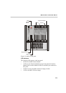
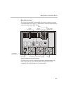
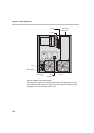
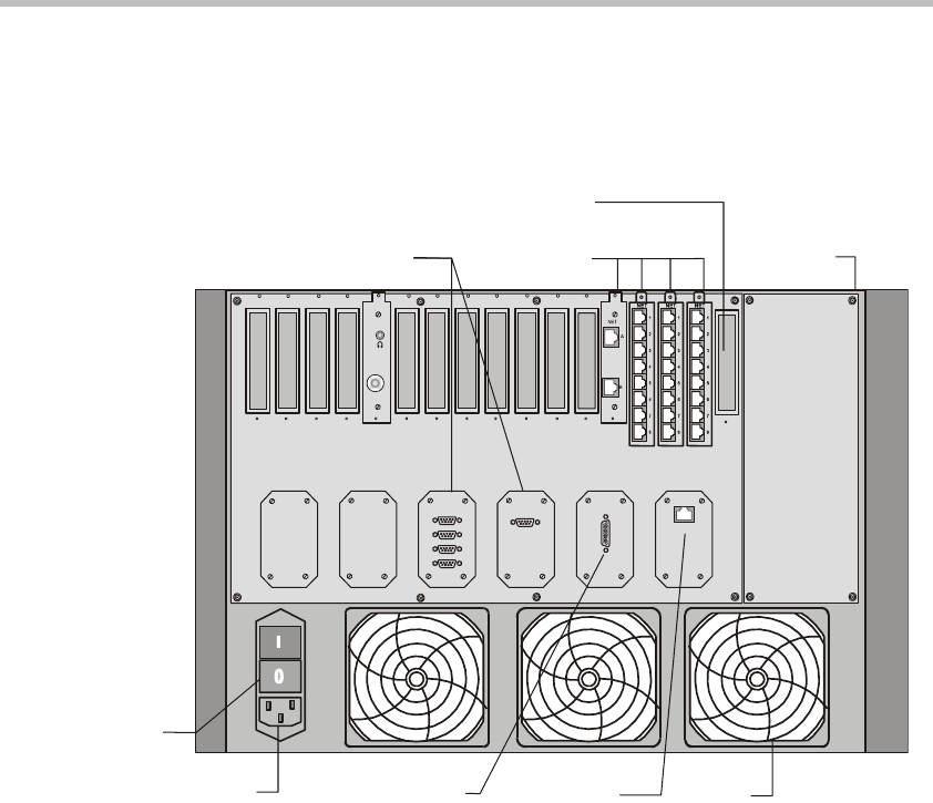
MGC Unit Rear Panel
The rear panel of the MGC-100 and MGC-50 contains a number of controls
for using the MGC unit. Figure 5-3 AND Figure 5-4 show the back panel and
labels all elements of the MGC-50/100.
Figure 5-3: MGC-100 rear panel controls
The main power switch is used during installation and replacement of the
main control unit only, since all other MGC-100 components are hot
swappable. The switch includes an AC circuit breaker.
LAN
ALARMSCOM 1
COM
MUSIC
LINE IN
AC Inlet
Main Switch
and Circuit Breaker
Main Control
Module Cover
Network
Connectors
RS232
Connectors
Fan
Dr
y
Contacts
RJ45 Connector
Slot A
10/100 Mbits