


Chapter 4 - Hardware Description
4-42
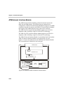
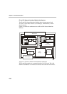
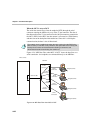
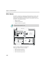
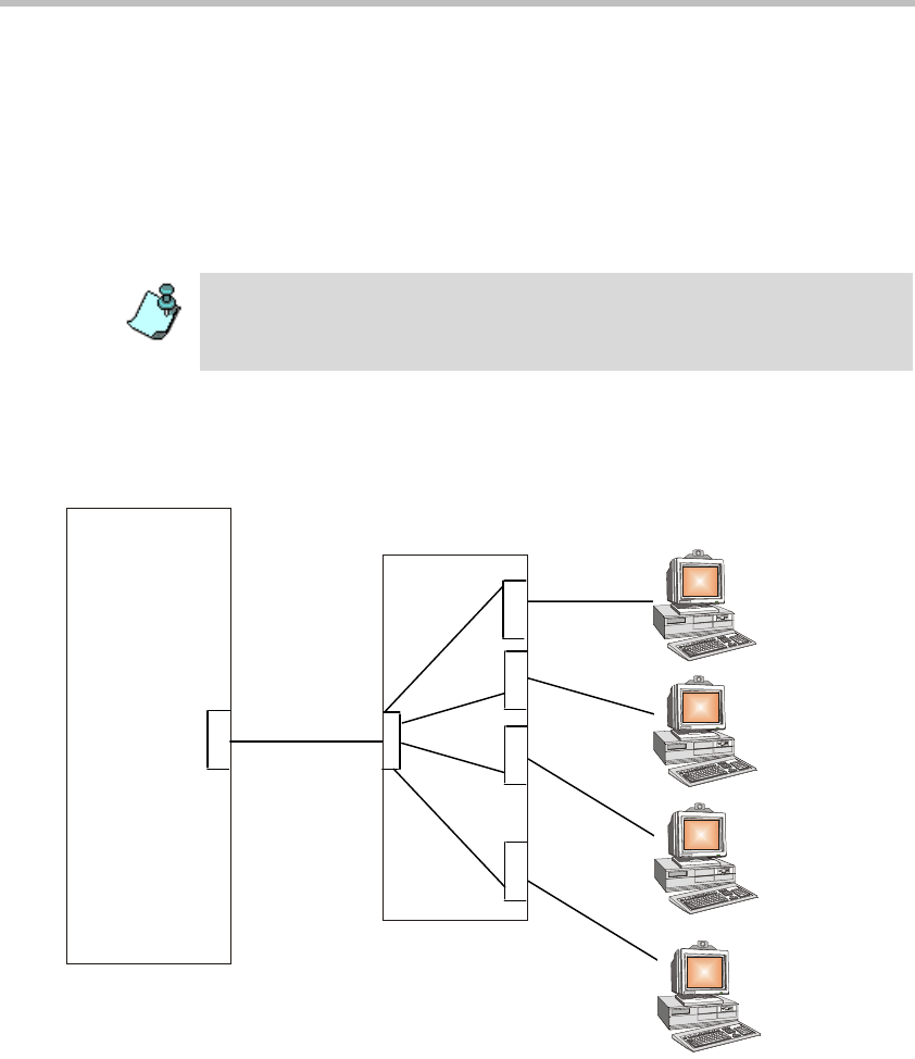
When the MCU is set as a DCE
The serial data stream flows from the endpoint (DTE) through the serial
connector entering the MPI box by way of the 37-pin connector. The data is
then directed from the 37-pin connector to the 160-pin connector connected to
the MCU (DCE). In the MCU the data stream is converted to a TDM format,
and then sent to the backplane information bus. Since this is a full duplex
communication, the data is also bi-directional.
Figure 4-24, “MPI Data Flow when MCU is DCE” shows the data flow on a
serial connection - the endpoints are connected directly to the MPI Box.
Figure 4-24: MPI Data Flow when MCU is DCE
The network clock is enabled only when the span coming from the DCE to the
MCU is active (i.e. handles a call). Therefore, the spans defined as Primary and
Backup clock must be connected first when starting a conference and
disconnected last when terminating the conference.
Endpoint (DTE)
Endpoint (DTE)
MCU (DCE)
Endpoint (DTE)
37- Pin
Connector
Endpoint (DTE)
Serial
Connection
Serial
Connection
Serial
Connection
Serial
Connection
37- Pin
Connector
37- Pin
Connector
37-Pin
Connector
MPI Box
160-Pin Cable