


MGC Hardware and Installation Manual
4-41
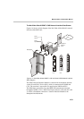
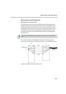
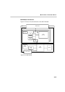
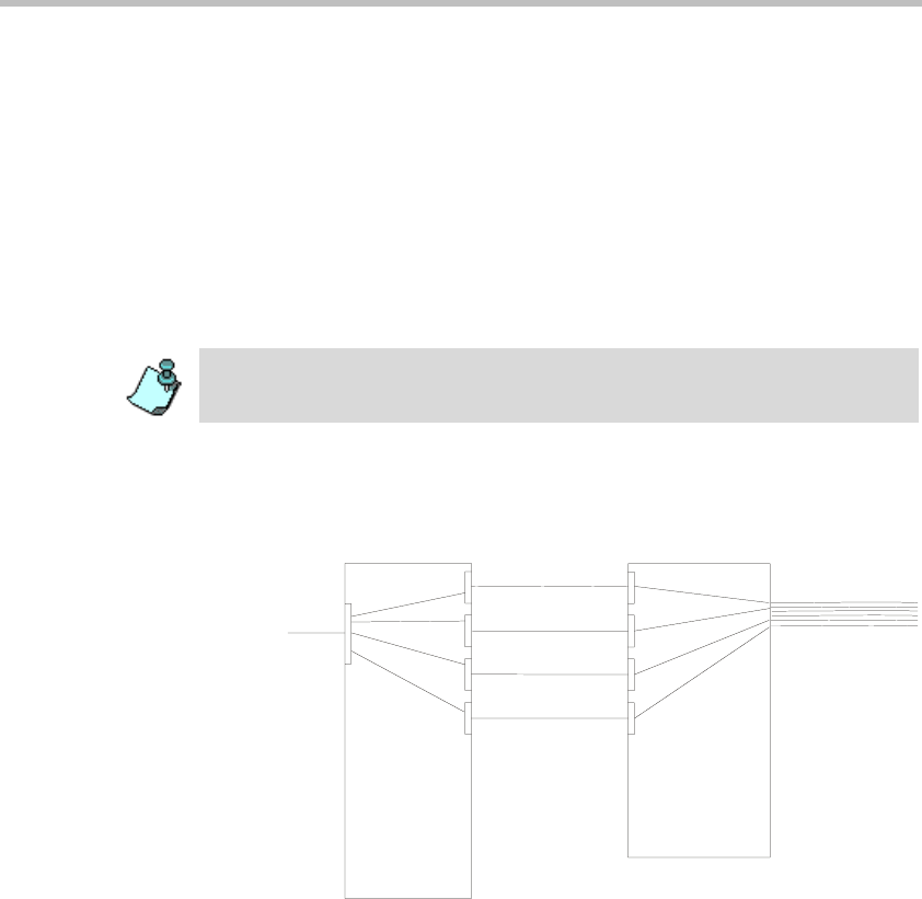
MPI-8 Network Interface Data Stream
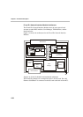
When the MCU is set as a DTE
The ISDN data stream flows from the ISDN telecommunication network
through the DCE to the serial port (37-pin connector) on the MPI box. The
data is then directed from the 37-PIN connector to the 160-PIN connector,
which gathers data from four different ports, and channels the data stream to
the 160-pin connector located on the MPI-8 front panel. The data is then
converted from serial format to TDM format and flown to the Backplane
information bus.
Since this is full duplex communication, the data is also flowing in the
opposite direction. Figure 4-22 shows the data flow on an ISDN data stream.
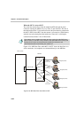
Figure 4-23: MPI Data Flow when MCU is DTE
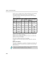
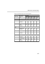
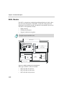
The master and the Backup clock must be set on spans of the same network
type.
T1 ISDN line
(23 channels)
C
h
a
n
n
e
l
s
1
-
6
C
h
a
n
n
e
l
s
7
-
1
2
C
h
a
n
n
e
l
s
1
3
-
1
4
C
h
a
n
n
e
l
s
1
5
-
1
6
Serial
connection
Serial
connection
37-PIN
connector
37-PIN
connector
160-PIN
connector
37-PIN
connector
37-PIN connector
T
o the 160-PIN connector
on the MPI-8 module
DCE
MPI Box