


MGC Hardware and Installation Manual
4-17
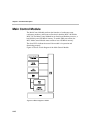
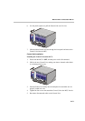
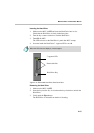
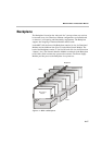
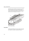
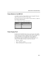
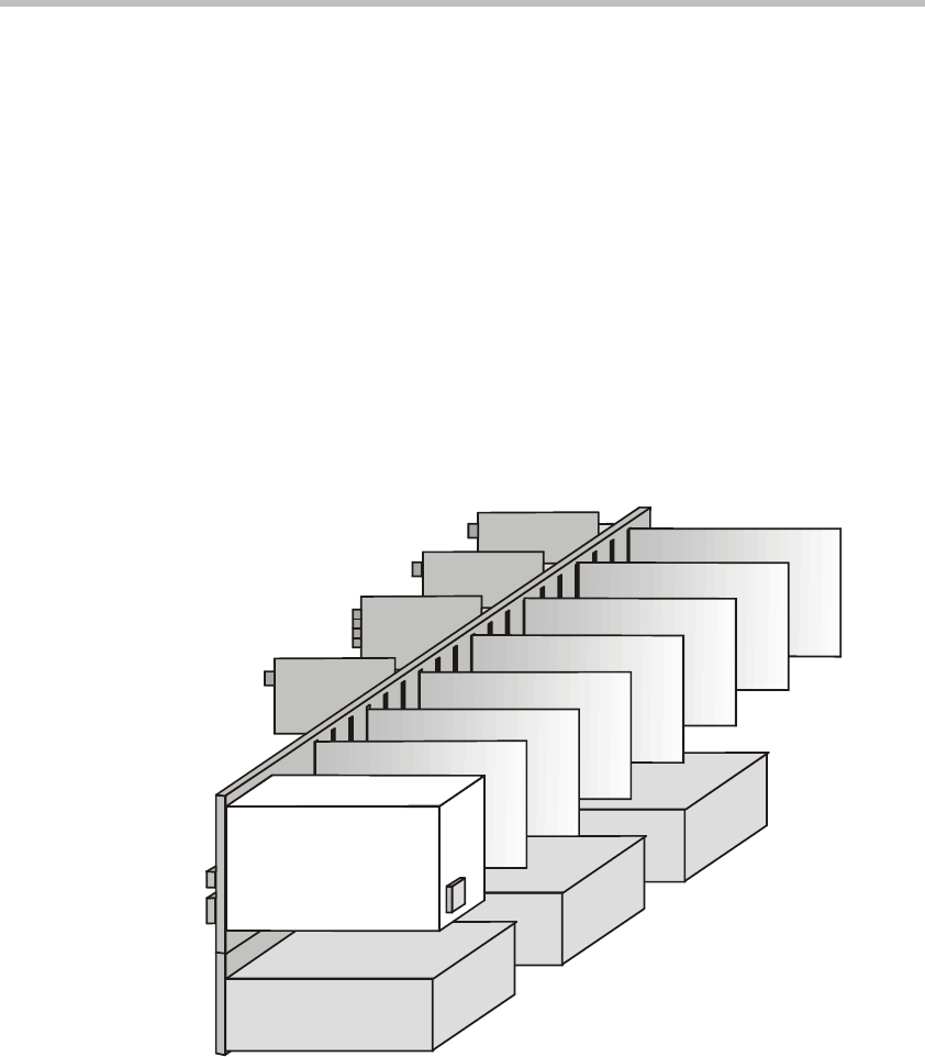
Backplane
The Backplane is based on the “universal slot” concept, where any card can
be inserted in any slot. Therefore, different configurations are formed based
on the users’ port capacity and functionality requirements. The Backplane
supports hot swapping of Function Modules and I/O cards.
In the MGC-100, the front of the Backplane contains 16 slots for Functional
Modules and an additional slot (Slot A) for the Main Control Module. The
back of the Backplane contains 17 slots for I/O cards (16 slots for I/O and one
“dummy” slot). The Network Interface Modules connected via the Backplane
to I/O cards, which connects the system to the network. The Power Supply
Module provides power to the Backplane via a power bus.
Figure 4-11: MGC-100 Backplane
ISDN Network I/F
ATM Network I/F
H.323 Network I/F
MUX
Audio
Video
Data
H.323 I/O
NET I/O
ATM I/O
MUSIC I/O
Rear
Backplane
Front
Main Control
Module
Power Supply
Module