


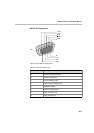
MGC Hardware and Installation Manual
A-5
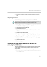
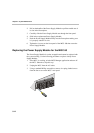
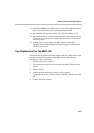
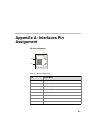
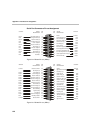
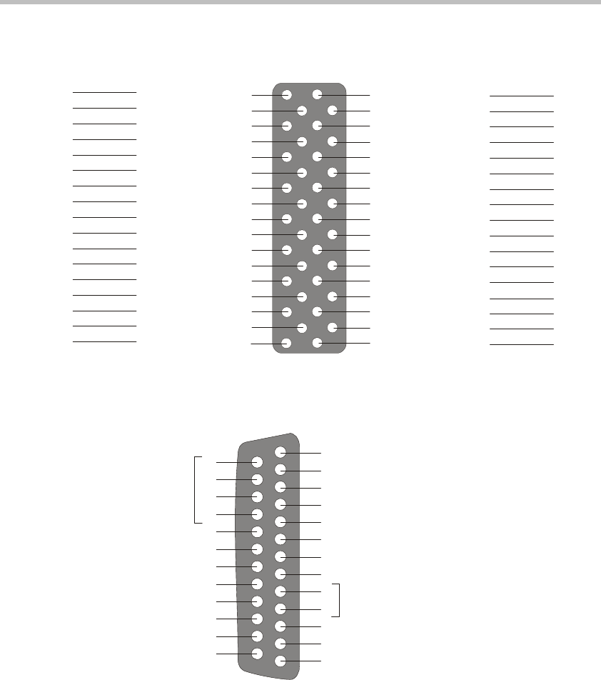
Figure A-6: V.35 Pin out (M-34 Connector)
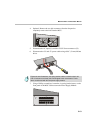
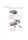
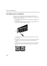
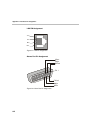
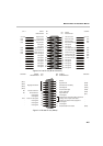
Figure A-7: RS-366 Pin out (DB-25)
A
C
E
H
K
M
P
S
U
W
Y
AA
CC
EE
HH
KK
MM
B
D
F
J
L
N
R
T
V
X
Z
BB
DD
FF
JJ
LL
NN
Chassis Ground
Request to Send
Data Set Ready
Data Terminal Ready
Unassigned
Unassigned
Transmitted Data (A)
Transmitted Data (B)
Terminal Timing (A)
Terminal Timing (B)
Transmit Timing (A)
Transmit Timing (B)
Unassigned
Unassigned
Unassigned
Unassigned
Unassigned
Signal Ground
Clear to Send
Data Carrier Detect
Ring Indicator
Unassigned
Unassigned
Receive Data (A)
Receive Data (B)
Receive Timing (A)
Receive Timing (B)
Unassigned
Unassigned
Unassigned
Unassigned
Unassigned
Unassigned
Unassigned
Common
DTE
DCE
DTE
-
-
DTE
DTE
DTE
DTE
DCE
DCE
-
-
-
-
-
Common
DCE
DCE
DCE
-
-
DCE
DCE
DCE
DCE
-
-
-
-
-
-
-
PIN
NO.
PIN
NO.
SIGNAL
DESIGNATION
SIGNAL
DESIGNATION
SOURCE
SO
UR
C
E
1
2
3
4
5
6
7
8
9
10
11
12
13
14
15
16
17
18
19
20
21
22
23
24
25
-
(DPR)
(ACR)
(CRQ)
(PWI)
(SG)
-
-
-
-
-
(DSC)
(PND)
Shield
Digit Present
Abandon Call and Retry
Call Request
Present Next Digit
Power Indication
Signal Ground
Unassigned
Unassigned
Unassigned
Distant Station Connected
Reserved for automatic calling equipment
testing. These 2 pins shall not be
wired in the data terminal equipment.
Digit Signal Circuits
Receive Common
Send Common
Unassigned
Unassigned
Data Line Occupied
Unassigned
Unassigned
Unassigned
(NB1)
(NB2)
(NB3)
(NB4)
RC
SC
-
-
DLO
-
-
-
PIN
NO.
PIN
NO.
SOURCE
SOURCE SIGNAL
DESIGNATION
SIGNAL
DESIGNATION