


3-1
3
System Architecture
The MGC unit is designed to provide maximum reliability, minimum
interruptions, and effortless maintenance. Removable active components are
accessed via the front panel to provide quick and easy serviceability.
Redundant power supplies are easily accessed via the front panel, ensuring a
fail safe operation (the MGC-50 is not redundant, therefore not hot-
swappable). Network connections on the back of the unit enable easy
module removal and prevent accidental disconnection.
All Functional Modules are front-removable and hot-swappable, allowing
servicing functions to be performed while the system is in operation.
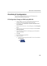
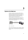
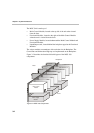
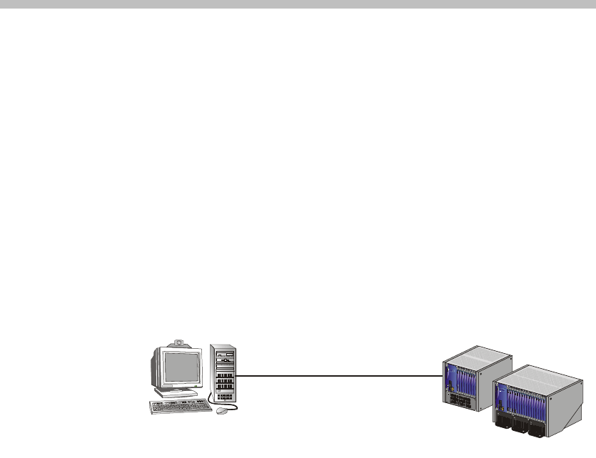
The operator accesses the MGC unit from an operator work station which is
connected to the MGC unit via an Ethernet interface or an RS-232 interface,
as shown in Figure 3-1, “MGC interfaces”.
Figure 3-1: MGC interfaces
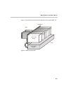
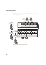
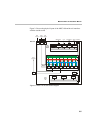
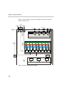
Figure 3-2, “MGC-100 Components” on page 3-2 and Figure 3-3, “MGC-50
components” on page 3-3 show the internal layout of the MGC-100 and the
MGC-50, respectively. All of the MGC modules and cards connect to the
backplane.
MGC-50
MGC-100
Operator Workstation
LAN / WAN / RS-232