


Altivar
®
58 TRX AC Drives
Wiring Recommendations
© 2000–2003 Schneider Electric All Rights Reserved
108
09/2003
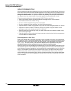
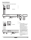
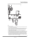
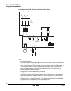
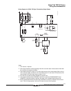
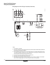
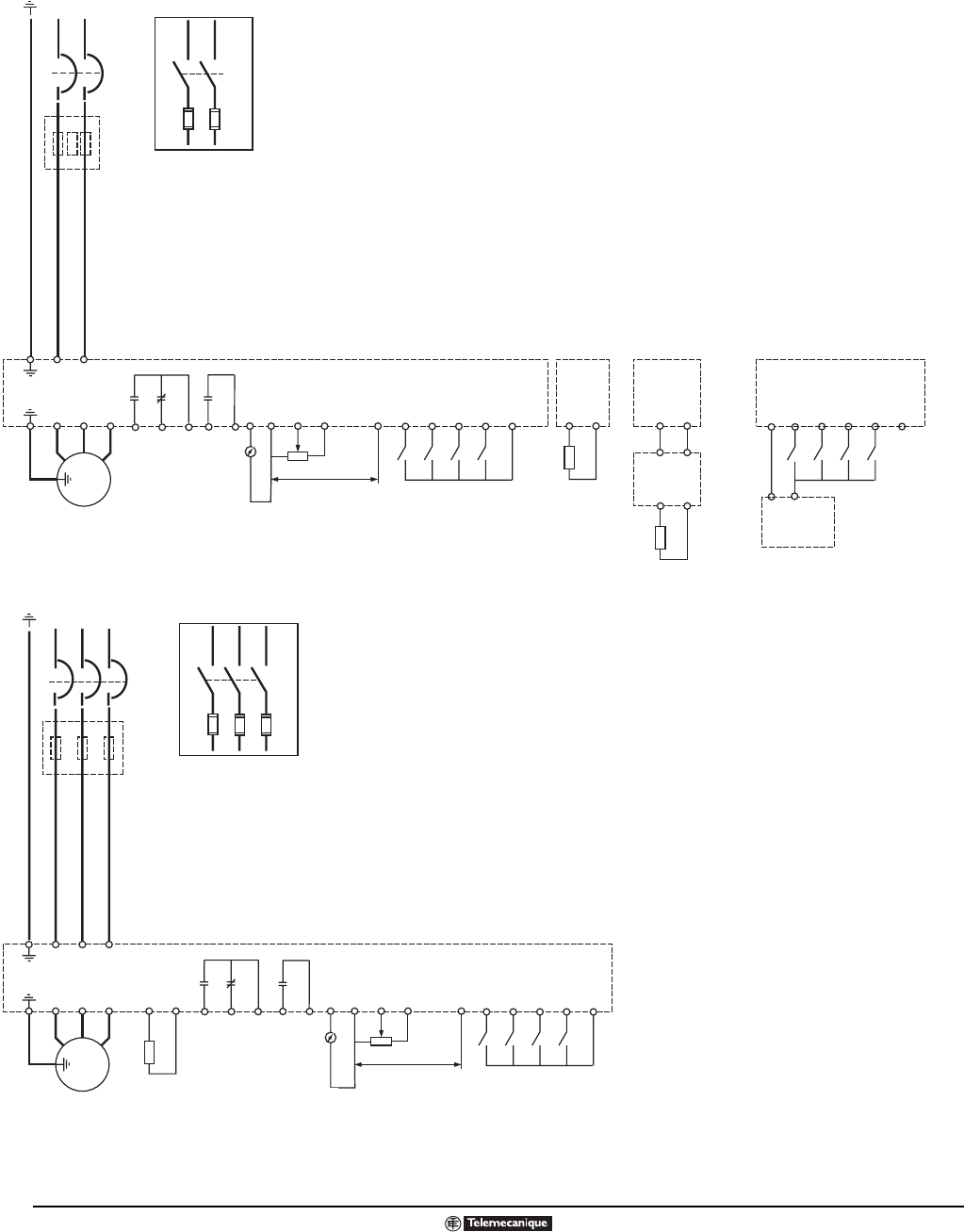
Wiring Diagrams for ATV58 TRX Type H and Type N Controllers
U
V
W
COM
(0 V)
AO1
AI1
+10
L1
U1
W1
V1
M
3 φ
L2
AI2
(3)
X - Y mA
(2)
R2A
R1C
R1B
R1A
R2C
(4)
(1)
LI1
LI2
LI3
LI4
+24
L1
L2
PA
PB
+
-
+
-
PA
PB
ATV58•
U09M2 and
U18M2
Brake Resistor
(if required)
Brake Resistor
(if required)
ATV58•
other
models
Braking
Module
F1
F2
(6)
or
(5)
Drive Fault
(fixed)
Output
Meter
(if used)
Programmable
LI1
COM
LI2
LI3
LI4
+24
(3)
0 V
+24 V
External 24 V
Power Supply
U
V
W
PA
PB
COM
(0 V)
AO1
AI1
+10
L1
U1
W1
V1
M
3 φ
L2
L3
LI1
LI2
LI3
LI4
+24
AI2
(7)
(1)
(3)
L1 L2 L3
Brake resistor
if required
F1
F2
F3
(6)
or
X - Y mA
(5)
R1A
R2A
R1B
R1C
Drive Fault
(fixed)
Output
Meter
(if used)
R2C
Programmable
(2)
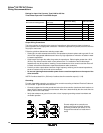
Single Phase
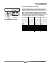
Notes:
1. Line reactor if required.
2. Fault relay contacts for remote signaling
of the drive controller state. Contact
state is shown with drive controller
deenergized or faulted.
3. Internal +24 V. When using +24 V
external supply, connect the 0 V to the
COM terminal. Do not use the +24 V
terminal on the control board, but
connect logic inputs to external +24 V.
4. When using dynamic braking on drive
controllers ATV58HU09M2 and U18M2,
the dynamic braking module, catalog
number VW3A58701, must be used.
See pages 34–37 for available braking
resistor kits.
5. Manual speed potentiometer (1–10 kΩ)
6. Branch circuit protection (circuit breaker
or fuses) must be installed.
7. See pages 34–37 for available braking
resistor kits.
Three Phase
single phase diagram (2) catalog.eps
Three phase diagram (catalog).eps