Altivar
®
58 TRX AC Drives
Type FVC Analog and Logic Outputs
73
09/2003
© 2000–2003 Schneider Electric All Rights Reserved
ATV58 TYPE FVC ANALOG OUTPUTS
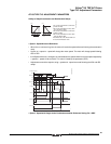
Signed Ramp (Code ORS)
When configured for signed ramp, the analog output provides a signal proportional to the drive
controller’s internal frequency ramp. This output is scaled to indicate rotation direction. AOL
corresponds to the maximum frequency (parameter tFr) in the reverse direction. AOH corresponds to
the maximum frequency (parameter tFr) in the forward direction. (AOH + AOL) divided by 2 corresponds
to zero frequency.
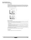
PID Setpoint (Code OPS)
The image of the PID regulator setpoint. AOL corresponds to the minimum setpoint. AOH corresponds
to the maximum setpoint.
PID Feedback (Code OPF)
The image of the PID regulator feedback. AOL corresponds to the minimum feedback. AOH
corresponds to the maximum feedback.
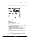
PID Error (Code OPE)
The image of the PID regulator error as a percentage of the sensor range (maximum feedback minus
minimum feedback). AOL correspond to -5%. AOH corresponds to +5%. (AOH plus AOL) divided by 2
corresponds to zero.
PID Integral (Code OPI)
The image of the PID regulator error integral. AOL corresponds to LSP. AOH corresponds to HSP.
ATV58 TYPE FVC LOGIC OUTPUTS
The programmable relay, R2, on the drive controller or the programmable logic output, LO, on an I/O
extension card can be configured for the following additional functions:
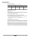
PID Error (Code PEE)
Can be assigned to R2 or LO. The logic output is active (state 1) or the relay is energized if the PID
regulator output error is greater than the threshold set by parameter PEr.
PID Feedback Alarm (Code PFA)
Can be assigned to R2 or LO. The logic output is active (state 1) if the PID feedback moves outside the
range set by parameters PAH and PAL.


