Altivar
®
58 TRX AC Drives
Communication Parameters
85
09/2003
© 2000–2003 Schneider Electric All Rights Reserved
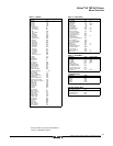
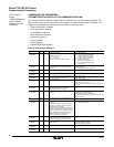
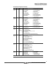
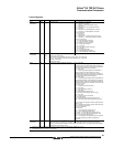
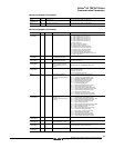
Control Registers
Word Code Units Description Possible Values or Range
W400
or 16#5FE7/1
CMD — Command word
[1]
Bit 0 = 0 and Bit 15 = 0: Not ready
Bit 0 = 1 and Bit 15 = 0: Ready
Bit 1 = 0: Return to “Switch On disabled” status
Bit 1 = 1: No action
Bit 2 = 0 and Bit 15 = 0: E-stop (rapid deceleration)
Bit 2 = 1: No action
Bit 3 = 0 and Bit 15 = 0: DRIVECOM stop command
Bit 3 = 1 and Bit 15 = 0: DRIVECOM run command
Bits 4 to 6: Reserved
Bit 7 = 0: No action
Bit 7 = 1: Reset faults
Bit 8 = 0 and Bit 15 = 1: Activate control via serial link
Bit 8 = 1 and Bit 15 = 1: Deactivate control via serial link
Bits 9 and 10: Reserved
Bit 11 = 0: Normal direction command
Bit 11 = 1: Reverse direction command
Bit 12 = 0: Motor run command (RUN)
Bit 12 = 1: Motor stop command
Bit 13 = 0: No action
Bit 13 = 1: Stop by DC injection command
Bit 14 = 0: No action
Bit 14 = 1: Fast stop command
Bit 15 = 0: DRIVECOM control register
Bit 15 = 1: Non-DRIVECOM control register
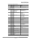
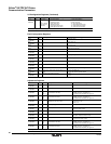
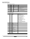
W401
or 16#5FE7/2
LFR 0.1 Hz
or
0.015
Hz
Serial link frequency reference.
[1]
LSP to HSP
Signed in two’s complement.
If bit 9 of CMI is 0, the resolution of LFR is 0.1 Hz (0–5000 = 0.0 to 500.0 Hz).
If bit 9 is 1, the resolution of LFR becomes approximately 0.015 Hz per count
(0–32767 = 0 to 500 Hz).
ATV58 Type FVC only.
W402
or 16#5FE7/3
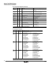
CMI — Internal control register (application program).
[1]
Bit0 = 0: No action
Bit0 = 1: Recall factory settings command. This bit
automatically resets to 0 after accepting the request; but if
CMI is a periodic variable, the PLC program must write it to
0 after the first request has been accepted.
[2]
Bit1 = 0: No action
Bit1 = 1: Save configuration/adjustments in EEPROM if
voltage is sufficient (no USF fault present). This bit
automatically resets to 0 after accepting the request; but if
CMI is a periodic variable, the PLC program must write it to
0 after the first request has been accepted.
[2]
Bit2 = 0: No action
Bit2 = 1: Recall configuration/adjustments in EEPROM. This
bit automatically resets to 0 after accepting the request; but
if CMI is a periodic variable, the PLC program must write it to
0 after the first request has been accepted. This bit is inactive
if the motor is running.
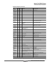
Bit3 = 0: No action
Bit3 = 1: External fault command (EPF)
Bit4 = 0: No action
Bit4 = 1: Ramp switching command
Bit5 = 0: No action
Bit5 = 1: Motor switching command; or
Open loop/closed loop switching (Type FVC only)
Bit6 = 0: No action
Bit6 = 1: Second torque limit command
Bit7: Leave this bit at 0
Bit8 = 0: Normal speed loop ramps (Type FVC only)
Bit8 = 1: Short-circuiting of speed loop ramps (Type FVC
only)
Bit9 = 0: Resolution of keypad or serial link speed reference
(LFR) is 0.1 Hz
Bit9 = 1: Resolution of keypad or serial link speed reference
(LFR) is approximately 0.015 Hz
Bits 10 to 11: Reserved
Bit12: Reserved
Bit13 = 0: Drive controller not locked at stop
Bit13 = 1: Drive controller locked at stop
Bit14 (NTO) = 0: Control with communication check
Bit14 (NTO) = 1: Control without communication check
Bit15 = 0: Parameter consistency check
Bit15 = 1: No parameter consistency check, drive controller
locked at stop. Switching this bit to 0 revalidates all
parameters.
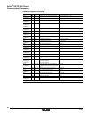
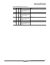
W403
or 16#5FE7/4
PISP 0.001 PI setpoint in serial link mode.
[1]
0 to 10,000
PISP is used only if an analog input is assigned to PIF: PID feedback. When using PISP, LFR (frequency
reference) and LFRD (speed reference) have no effect on the motor speed. The analog input for PID feedback
remains active in the serial link mode.
[1]
Parameter is reinitialized at the end of time-out unless bit 14 (NTO) of CMI (W402 or 16#5FE7/3) is set to 1.
[2]
The EEPROM life limit is 100,000 write operations.


