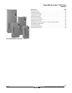
Class 8839 58M Enclosed AC Drives
Specifications
178
09/2003
© 2000–2003 Schneider Electric All Rights Reserved
h. The AC Drive will be able to develop rated
motor torque at 0.5 Hz (60 Hz base) in a
sensorless flux vector (SVC) mode using a
standard induction motor without an encoder
feedback signal.
2.08 PROTECTION
a. Circuit breaker coordination and short circuit
protection shall eliminate the need for current-
limiting and semiconductor fuses.
Manufacture who require the use of
semiconductor or current limiting fused will not
be approved.
b. The AC Drive shall be UL 508C listed for use
on distribution systems with [5,000 A,
10,000 A, 22,000 A, 65,000 A RMS] available
fault current. The AC Drive shall have a
coordinated short circuit rating designed to UL
508C and NEMA ICS 7.1 and listed on the
nameplate. The AC Drive shall not create a
hazard in the event of a short circuit at any
point within the AC Drive when it is connected
to a power source as specified on the
nameplate and protected as specified in the
instruction bulletin
c. Provisions shall be made to padlock the circuit
breaker in the off position when the enclosure
door is open.
d. Upon power-up the AC Drive shall
automatically test for valid operation of
memory, option module, loss of analog
reference input, loss of communication,
dynamic brake failure, DC to DC power supply,
control power and the pre-charge circuit.
e. The Power Converter shall be protected
against short circuits, between output phases
and ground; and the logic and analog outputs.
f. The AC drive shall have a minimum AC
undervoltage power loss ride-through of
200 msec. The AC Drive shall have the user-
defined option of frequency fold-back to allow
motor torque production to continue to
increase the duration of the powerloss ride-
through.
g. The AC drive shall have a selectable ride
through function that will allow the logic to
maintain control for a minimum of one second
without faulting.
h. For a fault condition other than a ground fault,
short circuit or internal fault, an auto restart
function will provide up to 255 programmable
restart attempts. The programmable time
delay before restart attempts will range from 1
second to 999 seconds.
i. The deceleration mode of the AC drive shall
be programmable for normal and fault
conditions. The stop modes shall include free-
wheel stop, fast stop and DC injection braking.
j. Upon loss of the analog process follower
reference signal, the AC Drive shall fault and/
or operate at a user-defined speed set
between software programmed speed
settings or last speed.
k. The AC drive shall have solid state thermal
protection that is UL Listed and meets UL
508C as a Class 20 overload protection and
meets IEC 947. The minimum adjustment
range shall be from .25 to 1.36% of the current
output of the AC Drive.
l. There shall be three skip frequency ranges
with a bandwidth of 5 Hz. The skip
frequencies shall be programmed
independently, back to back or overlapping.
2.09 ADJUSTMENTS AND CONFIGURATIONS
a. The AC Drive shall self-configure to the main
operating supply voltage and frequency. No
operator adjustments will be required.
b. Upon power-up, the AC Drive will
automatically send a signal to the connected
motor and store the resulting resistance data
into memory. The inductance data will be
measured during no-load operation when
operating at a frequency between 20-60 Hz.
The AC Drive shall automatically optimize the
operating characteristics according to the
stored data.
c. The AC Drive will be factory pre-set to operate
most common applications.
d. A choice of three types of acceleration and
deceleration ramps will be available in the AC
Drive software; linear, S curve and U curve.
e. The acceleration and deceleration ramp times
shall be adjustable from 0.1 to 999.9 seconds.
f. The volts per frequency ratios shall be user
selectable to meet variable torque loads,
normal and high-torque machine applications.
g. The memory shall retain and record run status
and fault type of the past eight faults.
h. Slip compensation shall be a software-
enabled function.
i. The software shall have a NOLD (no load)
function that will reduce the voltage to the
motor when selected for variable torque loads.
A constant volts/Hz ratio will be maintained
during acceleration. The output voltage will
then automatically adjust to meet the torque
requirement of the load.


