Altivar
®
58 TRX AC Drives
Dynamic Braking Resistor Kits
35
09/2003
© 2000–2003 Schneider Electric All Rights Reserved
Calculating Resistor Size
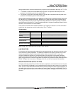
The standard dynamic braking (DB) resistor assemblies are suitable for a wide variety of drive system
stopping applications. However, when the driven machinery may present an overhauling load or large
inertia to the drive system, the suitability of the DB resistor assembly should be checked.
The suitability of a DB resistor assembly is determined by analyzing the mechanical system of the driven
machinery. From the analysis, the following key parameters are computed:
• The peak braking power required during stopping or speed changes (P
i
). The value of P
i
determines
the maximum allowable ohmic value of the DB resistor.
• The amount of power that must be absorbed (P
d
) for a given time (t
d
) by the DB resistors during
stopping or speed changes of the drive. The value of P
d
and t
d
determine the required time-current
characteristic of the DB resistor.
• The calculation of dynamic braking power requires V
db
.
•V
db
= 850 V for 460 V drives
V
db
= 375 V for 230 V drives
• The average power that must be dissipated by the DB resistor during an entire cycle of the machine
(P
a
). The value of P
a
determines the required continuous current rating of the DB resistor.
The following example illustrates the process:
Given
The application consists of a 5 hp, 460 Vac, 1740 rpm motor (N
base
= base speed) with a rotor
inertia of 0.28 lb-ft
2
. The motor is being controlled by an ATV58HU72N4 operating in the constant
torque mode. The motor is driving a machine with an inertia 10 times that of the motor with no
interposing gear box. The machine resistive (friction) torque is one-tenth of the rated motor torque
at full speed. The requirement is to stop in 5 seconds from rated speed at a rate of 2 cycles/minute.
Mechanical System Parameters:
Rated motor torque: T
n
= (hp x 5250)/N
base
= (5 x 5250)/1740 = 15.1 lb-ft
Machine cycle time: t
c
= (60 seconds)/(two operations per minute) = 30 seconds
Machine speed change during deceleration: N
d
= 1740 rpm - 0 rpm = 1740 rpm
Machine deceleration time: t
d
= 5 seconds
Mechanical system resistive (friction) torque: T
r
= (15.1 lb-ft)/10 = 1.51 lb-ft
Mechanical system overhauling torque: T
o
= 0.00 lb-ft
Mechanical system combined inertia: J
c
= 0.28 lb-ft
2
+ (10) x 0.28 lb-ft
2
= 3.08 lb-ft
2
Mechanical system inertial torque for a 5 second deceleration rate (as set by controller
deceleration ramp):
T
j
= Jc x (N
d
)/(308 x (t
d
)) = 3.08 x 1740/(308 x 5) = 3.48 lb-ft
Required braking torque from motor: T
b
= T
j
+ To - T
r
= 3.48 + 0.00 - 1.51 = 1.97 lb-ft
NOTE: The required braking torque must not exceed the motor’s ability to produce torque. For
inertial loads, including those depicted in the above examples, the required braking torque must
not exceed the torque producing ability of the dynamic braking unit with the recommended braking
resistor (approximately 1.5 times the motor rated torque for constant torque applications).
For machines that can continuously overhaul the motor, the value of overhauling torque (T
o
) minus
the resistive torque (T
r
) must not exceed the motor continuous torque rating at any speed.


