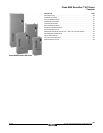
Class 8839 Econoflex™ AC Drives
Standard Features
187
09/2003
© 2000–2003 Schneider Electric All Rights Reserved
STANDARD FEATURES
The Econoflex controller includes:
• Circuit breaker disconnect with lockout capability.
• Insulated Gate Bipolar Transistor (IGBT) power converter with PWM output waveform.
• Door-mounted keypad.
• Form C AFC fault contact, rated 2 A at 120 Vac, wired to customer terminal block.
• Form C AFC run contact, rated 2 A at 120 Vac, wired to customer terminal block.
• Fire/Freezestat interlock location provided to customer terminal block.
• Factory enclosed line reactor (25 to 100 HP at 460 Vac, 15 to 50 HP at 208/230 Vac).
• Top and bottom conduit knockouts for Type 1 and Type 12K.
• Industrial rated control operators.
• UL 508C listed with NEMA ICS 7.1 compliance.
• Instruction bulletin 30072-450-10.
When Bypass is selected the Econoflex controller also includes:
• Isolation and Bypass Contactors, mechanically and electrically interlocked.
• AFC-OFF-BYPASS Selector Switch.
• TEST-NORMAL Selector Switch.
• Class 20 overload protection.
Power Circuit Descriptions
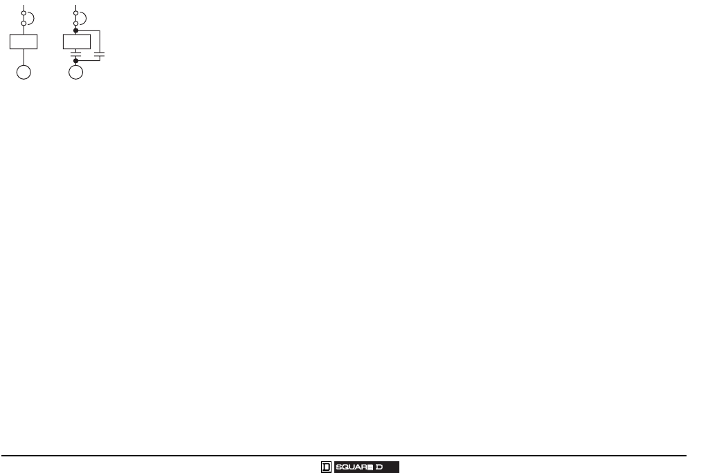
• Power Circuit W operates the motor from the power converter.
• Power Circuit Y operates the motor from the power converter or from full voltage line power, bypass.
The isolation and bypass contactors are mechanically and electrically interlocked. The two contactor
isolation/bypass configurations sequence the contactors to provide the isolation of the motor when it
is not running.
Test-Normal Selector Switch Description
The Test-Normal selector switch is mounted on the door of the controller and supplied with the bypass
circuit. The Test-Normal switch is used to test the power converter while operating the motor in bypass.
To use this function and maintain motor operation, place the following switches in these positions:
• AFC-Off-Bypass: Set the switch to Bypass to run the motor at full speed across the line.
• Test-Normal: Set the switch to Test.
• Hand-Off-Auto: Set the switch to Hand. Use the manual speed potentiometer to change the speed
reference and observe power converter operation.
Fire/Freezestat Interlock Description
User terminals are supplied for accepting a user supplied fire/freezestat interlock (normally closed).
When the user supplied contact is opened the drive output isolation contactor and bypass contactor
open and the motor stops.
AC AC
M
M
Power
Circuit W
Power
Circuit Y
PowerrCircuit W&Y copy.eps


