Altivar
®
58 TRX AC Drives
Assignment of Logic Outputs (R2 or LOx)
61
09/2003
© 2000–2003 Schneider Electric All Rights Reserved
ASSIGNMENT OF LOGIC OUTPUTS (R2 OR LOx)
The following is a description of the possible assignments of the Logic Outputs (R2 or LOx) on the
ATV58 TRX drive controller and the optional I/O Extension Cards.
Drive Running
The logic output is high (state 1, 24 Vdc nominal) if the motor is drawing current, or if a run command is
generated with a zero speed reference.
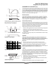
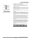
Output Contactor Control
The Output Contactor Control function enables the ATV58 TRX drive controller to control a contactor
located between the drive and the motor. The request to close the contactor is made when the Run
signal is given. The request to open the contactor is made when the Run signal is removed and the
deceleration ramp is completed.
The function is for use in applications where an air gap opening in the motor circuit is required. The
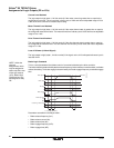
connection method illustrated in the diagram below is required.
This function may also be used:
• For applications involving machines where the operation requires power to the motor to be removed
when there is a stop to prevent any possibility of an untimely restart (for example, a materials
handling carousel where items are put down and then picked up manually).
• To implement a drive controller bypass circuit and to allow across-the-line operation of the motor. The
contactor on the drive controller is open in bypass mode to prevent applying line side power to the
output of the drive controller.
Reference Frequency Attained (Speed Attained)
The logic output is high (state 1, 24 Vdc nominal) if the output motor frequency is equal to the speed
reference value.
High Speed Attained
The logic output is high (state 1, 24 Vdc nominal) if the output motor frequency is equal to the high-speed
value.
Frequency Threshold Attained
The logic output is high (state 1, 24 Vdc nominal) if the output motor frequency is greater than or equal
to the configured frequency threshold. The frequency threshold is factory set at 50 or 60 Hz (depending
on the position of the 50/60 Hz switch) and has an adjustable range of low speed to high speed. Two
different levels can be configured to correspond to two logic output assignments.
U
V
W
U1
W1
V1
M
3 Phase
R2A
KM2
R2C
KM2 TS
120 VAC
TS = Transient suppressor
LineCont.eps
Wiring Diagram for Output Contactor
◆ See Specifications section for
contactor ratings.
◆


