


Altivar
®
58 TRX AC Drives
Assignment of Logic Inputs (LIx)
53
09/2003
© 2000–2003 Schneider Electric All Rights Reserved
ASSIGNMENT OF LOGIC INPUTS (LIx)
The following sections describe the possible assignments of the Logic Inputs
(LIx) on the drive controller and the optional I/O Extension Cards. Logic Input
1 (LI1) is configured for Run Forward when the drive controller is set for two
wire control and configured for STOP when the drive controller is set for three
wire control. In three wire control, Run Forward requires a logic input. Run
Reverse, if used, requires another logic input.
Reverse Operation
A logic input is assigned to reverse the direction of operation. The factory
default is for logic input LI2 to be used to reverse operation. To disable this
function (for example, when using the controller with a single-direction
motor), configure for no assignment or re-assign LI2 to another function.
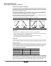
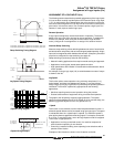
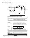
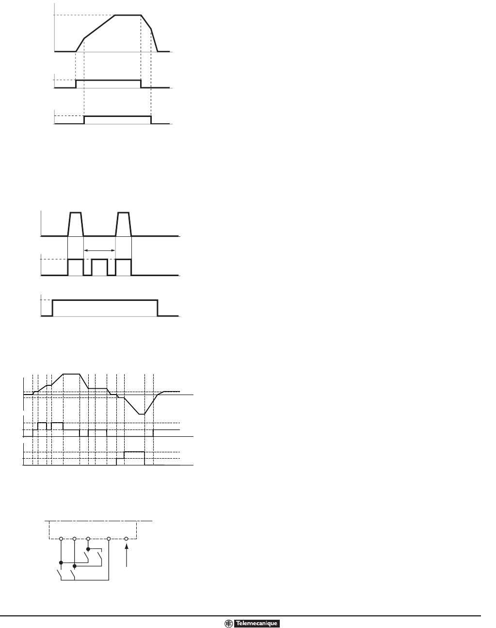
Alternate Ramp Switching
Alternate ramp switching allows switching between two sets of acceleration
and deceleration ramp times, with each set being adjusted separately. A logic
input can be assigned to switch between the two sets. A frequency threshold
may also be configured for ramp switching; see page 45.
Ramp switching is particularly suited for the following:
• Material handling applications that require smooth starting and approach.
• Applications involving fast, steady-state speed correction.
• High-speed lathes with limitation of acceleration and deceleration above
certain speeds.
An example of using a logic input (LI4) to switch between two sets of ramps
is shown to the left.
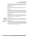
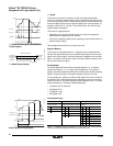
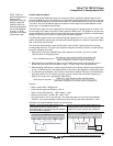
Jog Speed
This function pulses motor operation using minimum ramp times (0.1 s),
limited speed, and delay time between two pulses. To use this function,
assign a logic input to jog. Jog direction is provided by the operating direction
command. This function is particularly appropriate for the following
applications:
• Machines requiring some manual operation during the process.
• Gradual advancement of equipment during a maintenance operation.
The graph to the left portrays a typical jogging operation. The speed
reference adjusts between 0 and 10 Hz (preset at 10 Hz) and the delay (tm)
between jog pulses adjusts from 0 to 2 s (preset at 0.5 s).
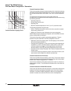
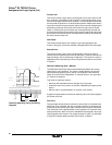
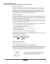
+ Speed
This function is also referred to as the motorized potentiometer function. It
allows the speed reference to be increased using one logic signal. The speed
is maintained when the + speed input is opened. The maximum speed is
given by the reference applied to the analog inputs. For example, connect AI1
to +10 Vdc. To use this function, one or two logic inputs must be re-assigned.
This function is appropriate for:
• Applications involving centralized control of a machine composed of
several sections operating in one direction.
• Controlling a material handling crane operating in two directions with a
pendant control station.
Examples of this function are shown in the illustration to the left.
F
o
rw
a
r
d
or
R
e
v
e
r
se
t
t
f
(
Hz
)
0
1
LI4
1
t
A
cc
2D
ec
2
A
cc
1D
ec
1
H
SP
T
or
q
Red.e
p
s
0
Acceleration 1/Deceleration 1: Adjustment 0.05 to 999.9 s, preset at 3 s
Acceleration 2/Deceleration 2: Adjustment 0.05 to 999.9 s, preset at 5 s
tm
f
(
Hz
)
F
o
rw
a
r
d
or
R
e
v
e
r
se
Jo
g
1
0
1
0
JogOp.eps
Forward
LSP
LSP
0
0
0
2nd action
1st action
aaaa a a a
bb
cc
d
Reverse
2nd action
1st action
Motor
Frequency
LI1
a c max. speed reference
bd
LIx
LIy
ATV58 terminal strip
+ 24 AIX
LI1: Forward
LIx: Reverse
LIy: +Speed
Activate a or c, then
activate b or d.
+ Speed Timing Diagram
+ Speed Wiring Example
+Speed double action (catalog).eps
+_- Speed Double Action.eps
Ramp Switching Timing Diagram
Jog Speed Timing Diagram