


LD Language Elements
116
SR2MAN01 11/2007
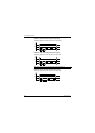
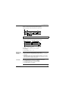
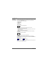
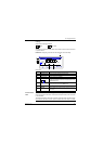
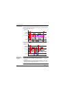
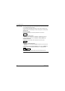
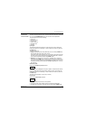
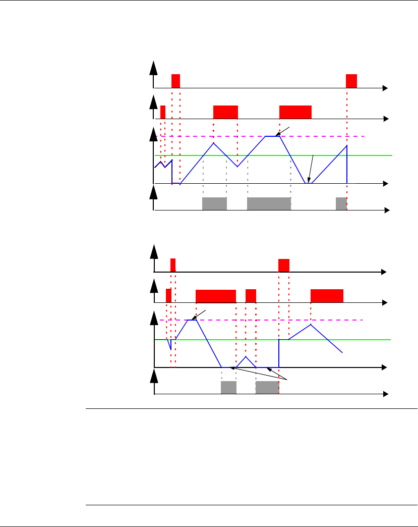
Timing Diagrams In the timing diagrams the blue curves represent the current value of the counter:
The following figure shows the operation of the counter in up-counting mode with
toward the preset value: TO mode:
The following figure shows the operation of the counter in upcounting mode from the
preset value: FROM mode:
Modifying the
Mode of a Coil or
a Contact
To modify the operating mode of a coil or a contact from the front panel of the smart
relay (the programming window displayed on screen), simply:
z Position the cursor on the symbol representing the coil mode or on the letter of
the contact,
z proceed as indicated in the paragraph Modifying an element,, p. 44, to scroll
through the possible modes for a coil or contact types possible (C for normally
open contact, c for a normally closed contact).
High saturation
Low
saturation
+32767
Initialization: R
Counting
direction: D
Current counter
value
Preset value
0
Output: C
Low saturation
+32767
Initialization: R
Counting
direction: D
Current counter
value
Preset value
0
Output: C
High saturation