LD Language Elements
96
SR2MAN01 11/2007
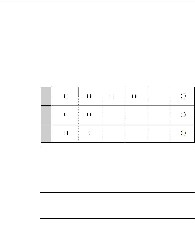
Example In the following example turning on and off a lamp is conditioned by the status of the
6 following inputs: I1, I2, I3, I4, I5 and IB.
The is on when:
z The I1, I4, I5 and IB inputs are set to the state 1,
and
z The I2, I3 are set to state 0.
Because the smart relay does not allow more than five contacts on a line, auxiliary
relays are used to control the lamp.
You choose to memorize the state of inputs I1, I4, I5 and IB using the auxiliary relay
M1 and memorize the state of inputs I2 and I3 using the auxiliary relay M2. The lamp
is controlled by relays M1 and M2, used respectively as normally open contact and
as normally closed contact.
Illustration:
Modifying the
Mode of a Coil or
a Contact
To modify the operating mode of a coil or a contact from the front panel of the smart
relay (the programming window displayed on screen), simply:
z Position the cursor on the symbol representing the coil mode or on the letter of
the contact,
z Proceed as indicated in the paragraph Modifying an element,, p. 44, to scroll
through the possible modes for a coil or contact types possible (M for normally
open contact, m for a normally closed contact).
Initialization Status of contacts on program initialization:
z Normally open mode (direct state) is inactive,
z Normally closed mode (reverse state) is active.
I1 M1
001
I2
002
M1
003
m2
Q1
I4 I5 IB
I3
M2


