LD Language Elements
88
SR2MAN01 11/2007
Introduction
Description In LD programming mode, an application can be created from the interface of the
front panel of the smart relay.
Here is detailed information on all possible elements of a ladder diagram in LD mode
that are recognized and used by smart relays.
To better understand the functions performed by each element, where necessary a
directly usable example is included.
Composition of
Ladder Diagrams
Smart relays accept 120-line diagrams.
z Each line is comprised of a maximum of 5 contacts.
z
Contacts must be attached to one coil, and the coil is not necessarily on the same line.
Sample Ladder
Diagram
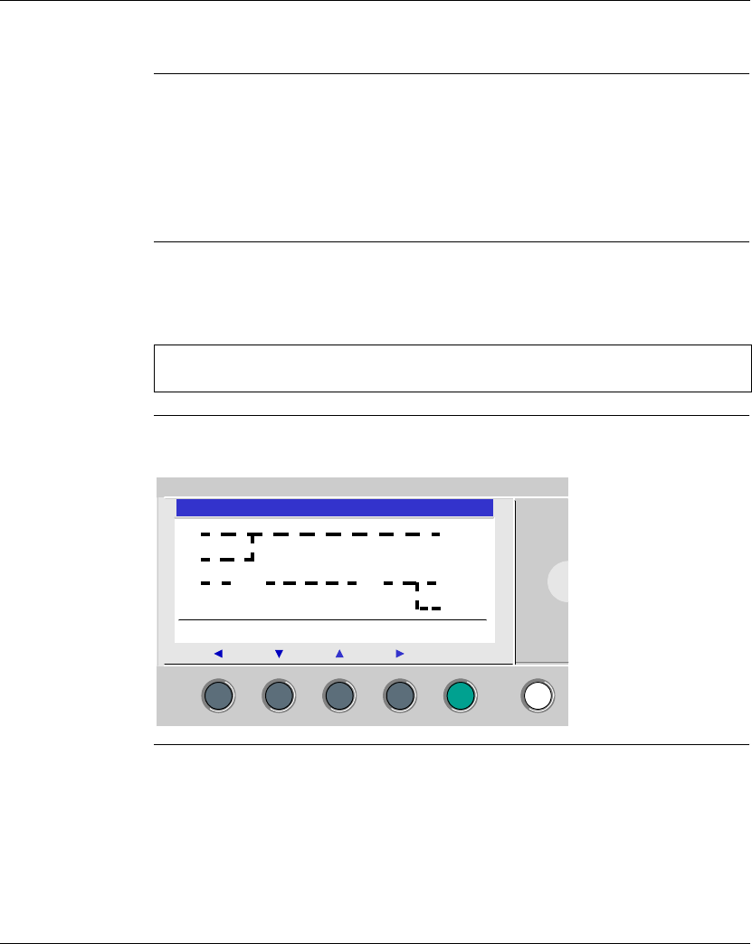
Below is an example of a ladder diagram, as it appears on the display of the front
panel of a smart relay:
Note: When an application requires more than five contacts to activate an action,
the auxiliary relays may be used.
2
I1 RT1
I2
I3 M3 Z1 SM1
TT1
Menu / OK


