LD Language Elements
SR2MAN01 11/2007 137
Example You wish to control a device connected to the Q2 output of the smart relay. You want
it to be active on the following two clock ranges:
z from Monday to Saturday, from 09:00 to 13:00.
z from Monday to Friday, from 15:00 to 19:00,
For this, the H1 Clock block is used and the following wiring diagram is created:
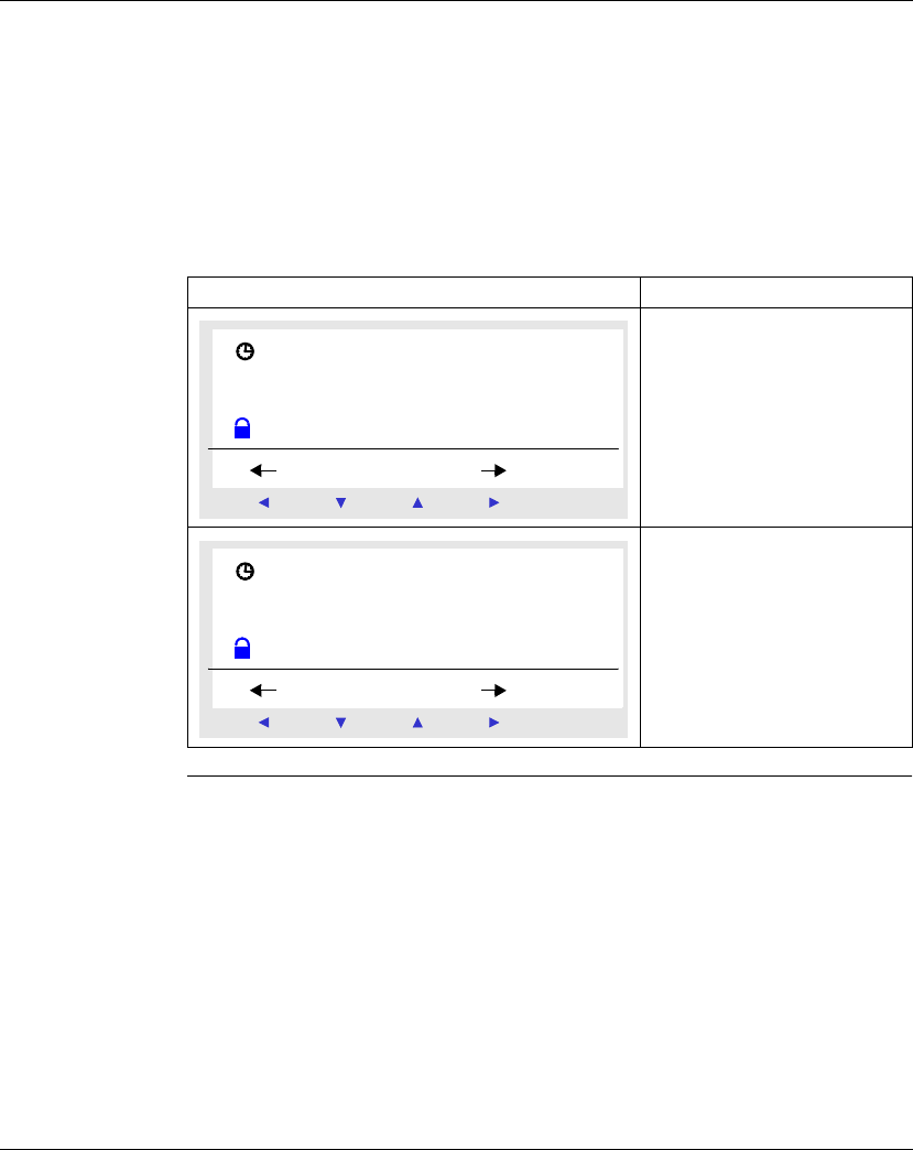
When entering the H1, Clock block, configure the operational ranges A and B as
described in the table below:
Screen Comment
First Slot A: From Monday to
Saturday, from 09:00 to 13:00.
Second Slot B: From Monday to
Friday, from 15:00 to 19:00,
H1-------------[Q2
Menu / OK
-+
H 1 J / S 0 1 2 3 4 5 _
A
H : M O N 0 9 : 0 0
H : M O F F 1 3 : 0 0
Menu / OK
-+
H 1 J / S 0 1 2 3 4 _ _
B
H : M O N 1 5 : 0 0
H : M O F F 1 9 : 0 0


