Implementing a Basic Application
154
SR2MAN01 11/2007
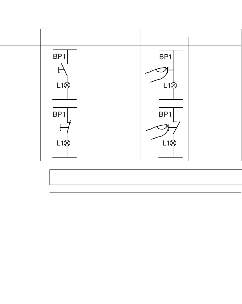
General Case The table below illustrates the operation of a pushbutton connected to the smart
relay. Pushbutton BP1 is connected to input I1 and lamp L1 is connected to output
Q1 on the smart relay.
Off delay Operating
Electrical diagram Smart relay symbols Electrical diagram Smart relay symbols
Pushbutton
normally open
I1 = 0
i1 = 1
I1 = 1
i1 = 0
Pushbutton
normally closed
I1 = 1
i1 = 0
I1 = 0
i1 = 1
Note: The reverse function may be applied to all of the contacts in a ladder
diagram, whether they represent outputs, auxiliary relays or function blocks.


