


188
ACK
[ ‘-----------
—.-
1 L—
—— ~
STROBE ~
‘-–r–-”
—1 r——————”
‘“s’ L—..— --l
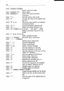
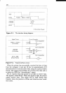
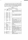
T: More than 0.5WWC
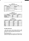
Figure F-1.
The interfacetimingdiagram.
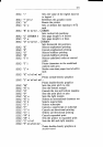
Siwd N’ame
!
Circuit Ew3mDle
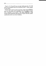
STROBE
(ToPrinter)
‘sat’’”
BUSY,ACK
(From Printer)
‘u:~a’ib’e
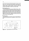
Figure F-2.
Typicalinterfacecircuit.
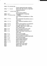
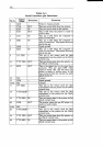
When the printer has successfully received the byte of data
from the computer it sets pin 10 low for approximately 2.75
microseconds (15 microseconds when using the optional buffer
board). This signal acknowledges the receipt of the data and so
is called the ACK (for “acknowledge”) signal.
Pin 11 reports when the printer is not able to receive data.
The signal is called BUSY. When this signal is high, the printer
cannot receive data. This signal will be high during data
transfer, when the printer is off-line and when an error condi-
tion exists.