


14
STP2002QFP
Sun Microelectronics
Fast Ethernet, Parallel Port, SCSI (FEPS) - STP2002QFP
PARALLEL PORT CHANNEL 4
4.1 Introduction
The parallel port interface implementation of FEPS is almost identical to the
one on the STP2000 Master I/O controller chip to leverage the existing device
driver. The only difference is that the DIR bit has to be set during a memory
clear operation. It allows the CPU to send data to the standard Centronics
printer in both programmed I/O and DMA modes. The parallel interface can
support bidirectional transfers using Xerox and IBM schemes. A 64-byte
buffer is used to buffer data to and from the channel engine interface and the
parallel port in DMA mode, depending on the direction of the transaction. In
synchronous mode, the port can support data transfer rate up to 4 Mbytes/s.
The parallel port interface also provides the data path to read the FCode
PROM when the FEPS chip is used on a SBus extended card. Two external
8-bit latches are needed to latch the MSB and LSB of the EPROM address.
Refer to the FEPS Application note for more details on this mode.
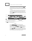
4.2 Parallel Port FIFO Operation
Between the parallel port and the SBus interface is a 64-byte FIFO (P_FIFO).
This FIFO is bypassed for slave accesses to the parallel port registers. Con-
sistency control ensures that all data written by the external device gets to
main memory in a deterministic manner, and is handled completely in hard-
ware. One of the consistency control mechanisms used on transfers to mem-
ory is draining of all P_FIFO data upon the access of any parallel port register.
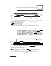
The conditions that cause data in the P_FIFO to be drained to memory are
as follows:
1. 4, 16, or 32 bytes (depending on P_BURST_SIZE) have been
written into the P_FIFO.
2. The P_INT_PEND bit in the P_CSR is set.
3. The CPU does a slave write to a parallel port internal register
other than the P_TST_CSR (writing P_ADDR does not cause
draining if P_DIAG is set).
4. The P_RESET or P_INVALIDATE bit in the P_CSR is set.
5. The P_ADDR register is loaded from P_NEXT_ADDR when
P_DIAG is not set.