


23
STP2002QFP
Fast Ethernet, Parallel Port, SCSI (FEPS) - STP2002QFP
Sun Microsystems,
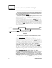
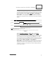
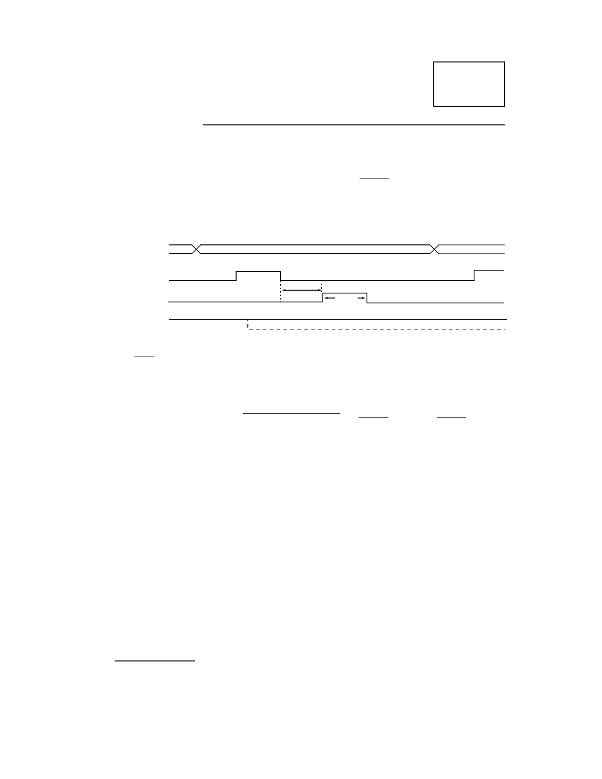
as required to gate further transfers but not as a handshake signal. The oper-
ation of the interface as defined assumes the bidirectional sense of each signal
has been configured as follows: DIR=1, DS_DSEL=1, ACK_DSEL=1,
BUSY_DSEL=1. The configuration of P_BSY (PP_BSY) as an output is
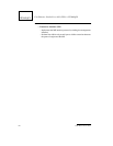
suggested to avoid potential data loss. Reference the data transfer diagram in
Figure 6.
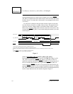
Figure 6.
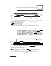
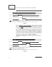
4.3.1.3.3 Handshake with BUSY: (BUSY_OP=1, ACK_OP=0)
Data transfers are acknowledged using P_BSY (PP_BSY). P_BSY
(PP_BSY) will be generated off of the leading edge of P_D_STRB (PP_STB)
and will remain active for the period specified by DSS (plus 3 to 4 SBus
clocks) beyond the end of P_D_STRB (PP_STB). The operation of the inter-
face as defined assumes the bidirectional sense of each signal has been con-
figured as follows: DIR=1, DS_DSEL=1, ACK_DSEL=X,
BUSY_DSEL=1. The configuration of P_ACK as an input will not hinder the
operation of the interface as far as handshaking is concerned. If P_ACK is
configured as an output, it will remain low or inactive. Reference the data
transfer diagram Figure 7.
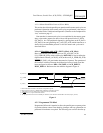
P_DATA (I)
P_D_STRB
(I)
P_ACK (O)
DSS
DSW
1
2
3
1. Acknowledge position relative to data strobe (DSS - hardware configuration register).
2. Acknowledge width (DSW - hardware configuration register).
3.
P_BSY will be asserted if required.
4. All signal polarities shown are at the HIOD pins. Polarities on the interface cable should be inverted (except P_DATA).