


15
STP2002QFP
Fast Ethernet, Parallel Port, SCSI (FEPS) - STP2002QFP
Sun Microsystems,
None of these conditions will cause draining if P_ERR_PEND = 1, indi-
cating that a memory error has occurred. If condition 4 or 5 occurs when the
P_ERR_PEND bit is 1, the P_FIFO will be invalidated and all dirty data will
be discarded.
4.3 Bidirectional Parallel Port Interface
The parallel port can operate unidirectionally or bidirectionally in either a
programmed I/O mode or in a DMA mode. The hardware interface can be
configured to operate with a wide range of devices through the following
mechanisms:
• Bidirectional signal configuration for the interface control signals—
data strobe, acknowledge, and busy. Each control signal can be indi-
vidually configured as a unidirectional or bidirectional signal.
• Programmable pulse widths for all generated signals and programma-
ble data setup time for data transfers.
• Programmable protocol definition for all combinations of acknowl-
edge and busy handshaking.
This interface configuration capability will allow operation over a wide
range of data transfer rates and protocol definitions.
4.3.1 DMA Mode
Since no software intervention is required for data transfer, the interface pro-
tocol and timing required must be programmed via the configuration regis-
ters. DMA transfers are initiated/enabled by setting the P_EN_DMA bit of
the P_CSR. The operation of the interface is dependent on the direction of
transfer and the protocol selected as described below.
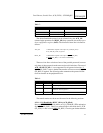
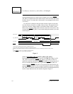
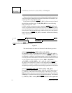
4.3.1.1 Unidirectional Operation (Transfers to the Peripheral Device)
This mode of operation is the Centronics implementation of a unidirectional
parallel port. Operation of the parallel port in this mode requires the direction
control bit (DIR) of the transfer control register (TCR) to be 0. Timing vari-
ations are handled via the DSS (data setup to data strobe) and DSW (data
strobe width) bits of the hardware configuration register. The timebase for
programmability is the SBus clock. The DSS parameter (7 bits) can be pro-
grammed from a minimum of 0 SBus clocks to 127 SBus clocks in steps of
one SBus clock. The DSW parameter (7 bits) is also programmed in steps of
one SBus clocks, however when DSW= 0, 1, 2, or 3, data strobe width is de-