


D 13373.08
NOVEMBER 2007
MPS
Table of
Contents
Gateway Conguration
TANDBERG MPS
ADMINISTRATOR GUIDE
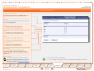
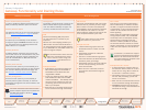
How to enable Gateway Funtionality
In order to enable the Gateway functionality in the
MPS, the Gateway Software option must be set.
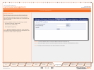
Gateway Software Option
The software option key is set in the web interface,
see the System Configuration > Upgrade section.
About the Option Key
An option key for the Gateway can be obtained
through the regular TANDBERG channels. The op-
tion key states how many Gateway sessions the
MPS is able to run in parallell.
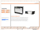
Gateway Sessions
A Gateway session requires 2 ports (one for the
source side and one for the destination side), thus
making 80 the maximum number of Gateway ses-
sions for the MPS 800. For MPS 200 the maxi-
mum is 20 sessions.
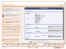
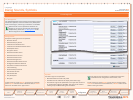
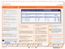
Gateway Calls Overview
Once the correct option key for the Gateway is en-
tered (and the system restarted), the web interface
will include a Gateway Calls Overview page, see
the Overview > Gateway Calls Overview section.
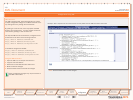
Gateway Configuration
Once the correct option key for the Gateway is
entered (and the system restarted), an extra tab
for Gateway Configuration will also be added to the
web interface.
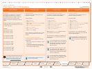
Gateway Functionality and Dialling Rules
About Dialling RulesGateway Functionality
For further information about how the video
system endpoint supports TCS-4 please see
the MXP Administrator’s Guide on http://
www.tandberg.com.
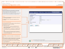
IVR + TCS-4
This call type is the same as described in
IVR but extended by an additional method,
the TCS-4, to signal the extension address
to the Gateway. In this mode the extension
number can be indicated with IVR or with
TCS-4 signalling.
TCS-4 allows an H.320 based videoconfer-
encing endpoint (ISDN, V.35, V.35RS366
and G.703) to dial an IP endpoint directly,
without having to (manually) enter the
extension number by DTMF. The endpoint
will send the extension number as a TCS-4
signal to the Gateway. If no TCS-4 extension
is sent from the endpoint, then IVR will be
used.
To use TCS-4, it needs to be support-
ed by the videoconferencing endpoint.
Refer to the Administrator’s Guide of
the videoconferencing endpoint to see
how TCS-4 is supported.
Example with IVR + TCS-4:
A videoconferencing endpoint calls into 1.
the Extension Dial In number of an IVR +
TCS-4 service, using <Dial In number of
this service>*<extension number>.
The Gateway starts to call the IP endpoint 2.
and the “Call proceeding” picture and
sound are activated.
When the call is connected audio and vid-3.
eo are transmitted through the Gateway.
TANDBERG endpoints allow storing the 4.
complete dial string in the Phone Book to
automate dial through.
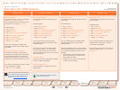
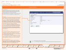
IVR Services
Interactive Voice Response (IVR), also called
extension Dial In, provides you with a single
Dial In number. The caller uses telephone
tones (DTMF) to enter the extension address
of the endpoint to be called. It is an auto-
mated answering system that directs the call
to the endpoint indicated by the caller.
IVR is useful when you have limited
PRI numbers on your PRI line.
Example with IVR:
A videoconferencing system calls into 1.
the Extension Dial In number of an IVR
service.
The Gateway activates the ‘Welcome’ 2.
picture and sound.
The user of a videoconferencing system 3.
enters the extension (H.323 E.164 Alias)
followed by the # (pound-sign).
The Gateway starts to call the IP endpoint 4.
and the “Call proceeding” picture and
sound are activated.
When the call is connected, the audio 5.
and video are transmitted through the
Gateway.
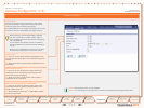
DID
Direct Inward Dialling (DID) will provide
you with direct Dial In numbers for your
endpoints.
DID will do a direct mapping between your
ISDN number and the H.323 E.164 Alias. If
you have assigned a range of ISDN numbers
to your ISDN PRI line, each ISDN number will
map to a single IP endpoint.
We recommend that if more than one
PRI line is used all PRI lines should
have a common number range, see
Trunk Groups in the PRI Board Con-
figuration section.
Example with DID:
A DID dialling rule exists that maps the 1.
PRI number range from 67124000 to
67124050 to the H.323 E.164 Alias
range 94000 - 94050.
To call an IP endpoint with H.323 E.1642.
Alias 94020 from ISDN, dial the ISDN
number 67124020. • The Gateway starts
the call to the IP endpoint and the “Call
proceeding” picture and sound are initi-
ated to your endpoint.
When the call is connected audio and vid-3.
eo are transmitted through the Gateway.
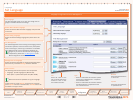
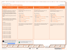
Dialling Rules
The dialling rules must be set in order for the
MPS to handle different types of Gateway
calls. The different Gateway call types sup-
ported by the MPS are described below.
113
Introduction
Quick
Setup
Using
the MPS
System
Status
System
Configuration
Installation
MCU
Configuration
Technical
Descriptions
Appendices
Main
Gateway
Configuration