


D 13373.08
NOVEMBER 2007
MPS
Table of
Contents
TANDBERG MPS
ADMINISTRATOR GUIDE
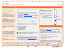
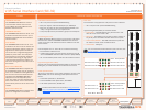
Chassis Media Processing Board Interface
Media Processing Board
Add-on boards for media processing are installed in adjacent slots in the
chassis.
The Media Processing Boards are handling the following functions:
Video processing. See • Video Features in the Technical Descriptions
section for details.
Audio processing. See • Audio > Create Conference in the Using the MPS
section for details.
Transcoding. See • Transcoding and Ratematching in the Technical De-
scriptions section for details.
Encryption. See • Secure Conference (Encryption) in the Technical De-
scriptions section for details.
Continuous Presence/Voice Switching. See • Video Features in the Tech-
nical Descriptions section for details.
TANDBERG MPS 800 has support for up to 8 Media Processing Boards.
TANDBERG MPS 200 has support for up to 2 Media Processing Boards.
Each Media Processing Board gives:
5 fully featured conferences•
20 video sites @ 384kbps•
16 audio sites @ 64kbps•
One media board is, in conjunction with a network interface card,
capable of a total of 7680 kbps for H.320/ISDN calls. For IP video
calls without encryption it can handle 15360 kbps.
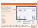
Two different IP Networks
If your TANDBERG MPS is connected to two different IP Networks utiliz-
ing both of the Ethernet ports (LAN and Enet2) on the System Controller
Board, you need to pre-define the Media Processing Boards to Network
#1 or Network #2. This is done in the Media Board Configuration in the
System Configuration section, by choosing either Network ID 1 or 2 for the
respective Media Processing Boards.
4 LEDs
10/100 BASE T
(Ethernet 10/100)
Alarm
Alarm
Active
Power
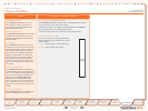
Advanced Video Option
A Media Processing Board can be purchased with or without the Advanced
Video Option (AVO). See Video Features in the Technical Description sec-
tion for further information.
All video participants will use one Advanced Video Option. In addition
one Advanced Video Option will be used if Dual Stream is enabled in the
conference.
The Advanced Video Option gives support for the following:
Continuous Presence•
Dual Stream - support for both DuoVideo•
TF
, H.239 and BFCP
Custom Video Formats (Digital Clarity•
TF
)
Best Impression•
TF
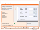
All Media Boards should be connected to the IP network and be given an
IP address to work properly, see Media Board IP Configuration for details.
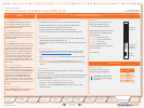
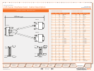
Media Processing Board Interface
Network Interfaces
Advanced Video Option
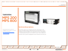
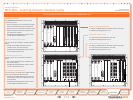
TANDBERG MPS 800
The TANDBERG MPS 800 has a 9U-19”
rack-mountable chassis that can host
up to 8 Media Processing Boards and 4
Network Interface Cards.
TANDBERG MPS 200
The TANDBERG MPS 200 has 3U-19” rack-
mountable chassis that can host up to 2
Media Processing Boards and 2 Network
Interface Cards.
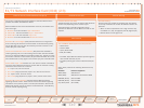
Front Chassis
The TANDBERG MPS chassis is 19” rack-
mountable. On the front of the chassis is a
Liquid Crystal Display (LCD) for initial con-
figuration and basic system information.
You will also find 4 Light Emitting Diodes
(LEDs) for power status. The backplane
of the chassis is provided with advanced
CompactPCI technology for high speed
communication between the boards. You
will find 3 cooling fans in the lower front of
the chassis.
Rear Chassis MPS 800
The TANDBERG MPS 800 is shipped with
2 hot-swappable power units for configura-
tions of 1 to 3 Media Processing Boards. If
the unit has more than 3 Media Process-
ing Boards the TANDBERG MPS 800 is
equipped with 3 hot-swappable power
units. The power units are installed at the
back of the chassis. You will also find the
power switch/connector at the back of the
chassis.
Rear Chassis MPS 200
The TANDBERG MPS 200 is shipped with 1
power unit integrated in the chassis.
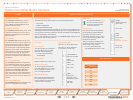
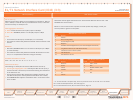
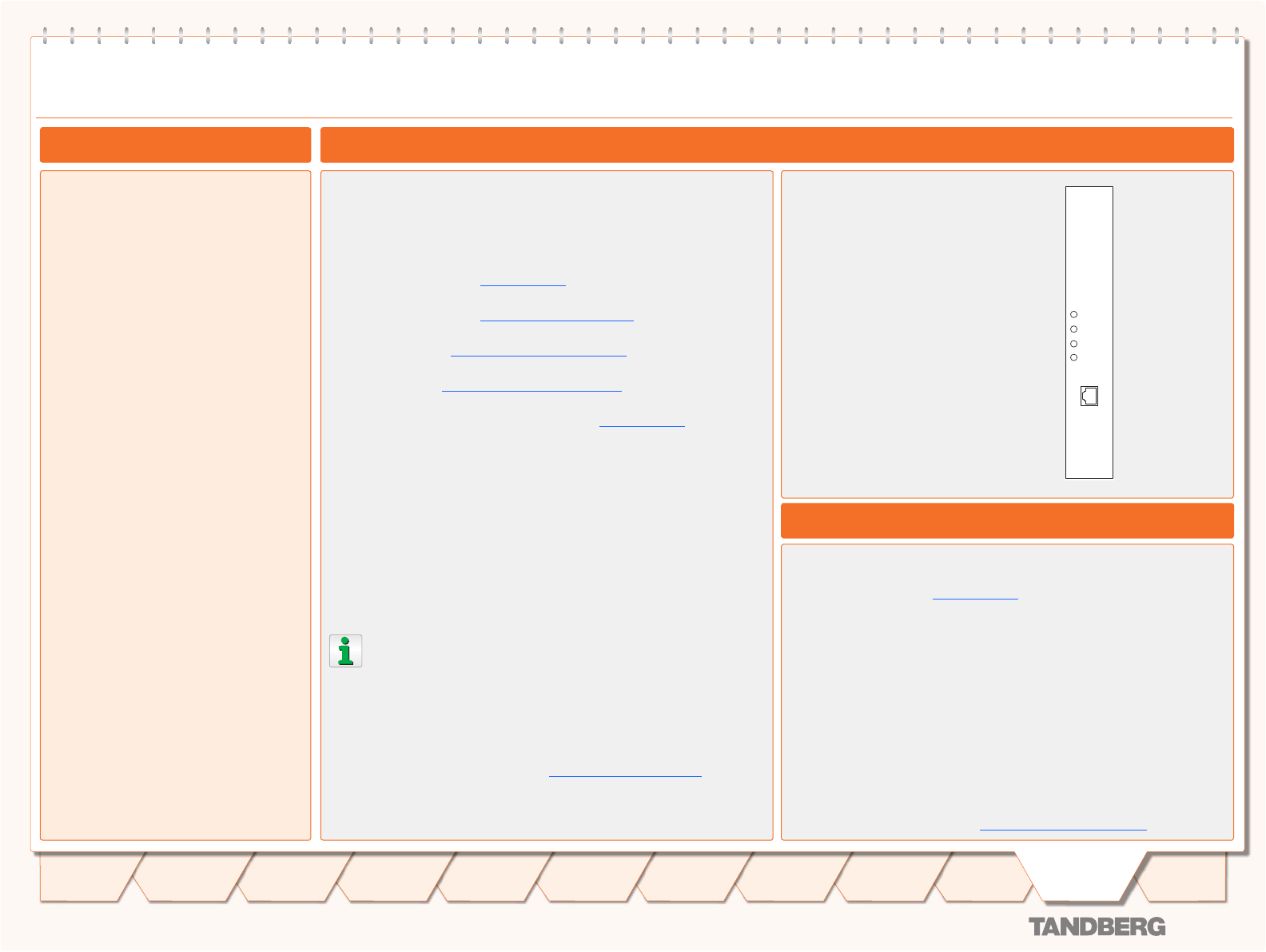
Front View
The Media Processing Board is equipped
with LAN interface for H.323 media:
1xLAN/Ethernet (RJ-45) 10/100 Mbps•
4 Light Emitting Diodes (LEDs) for board
status.
Alarm1. : Red Alarm indicates that the
Ethernet link is lost
Alarm2. : Flashes during startup and/
or media processing board applica-
tion failure.
Active3. : Green in normal operation
Power4. : Green in normal operation
147
Introduction
Quick
Setup
Using
the MPS
System
Status
System
Configuration
Installation
Gateway
Configuration
MCU
Configuration
Appendices
Main
Technical
Descriptions