


D 13373.08
NOVEMBER 2007
MPS
Table of
Contents
TANDBERG MPS
ADMINISTRATOR GUIDE
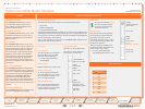
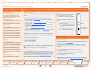
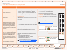
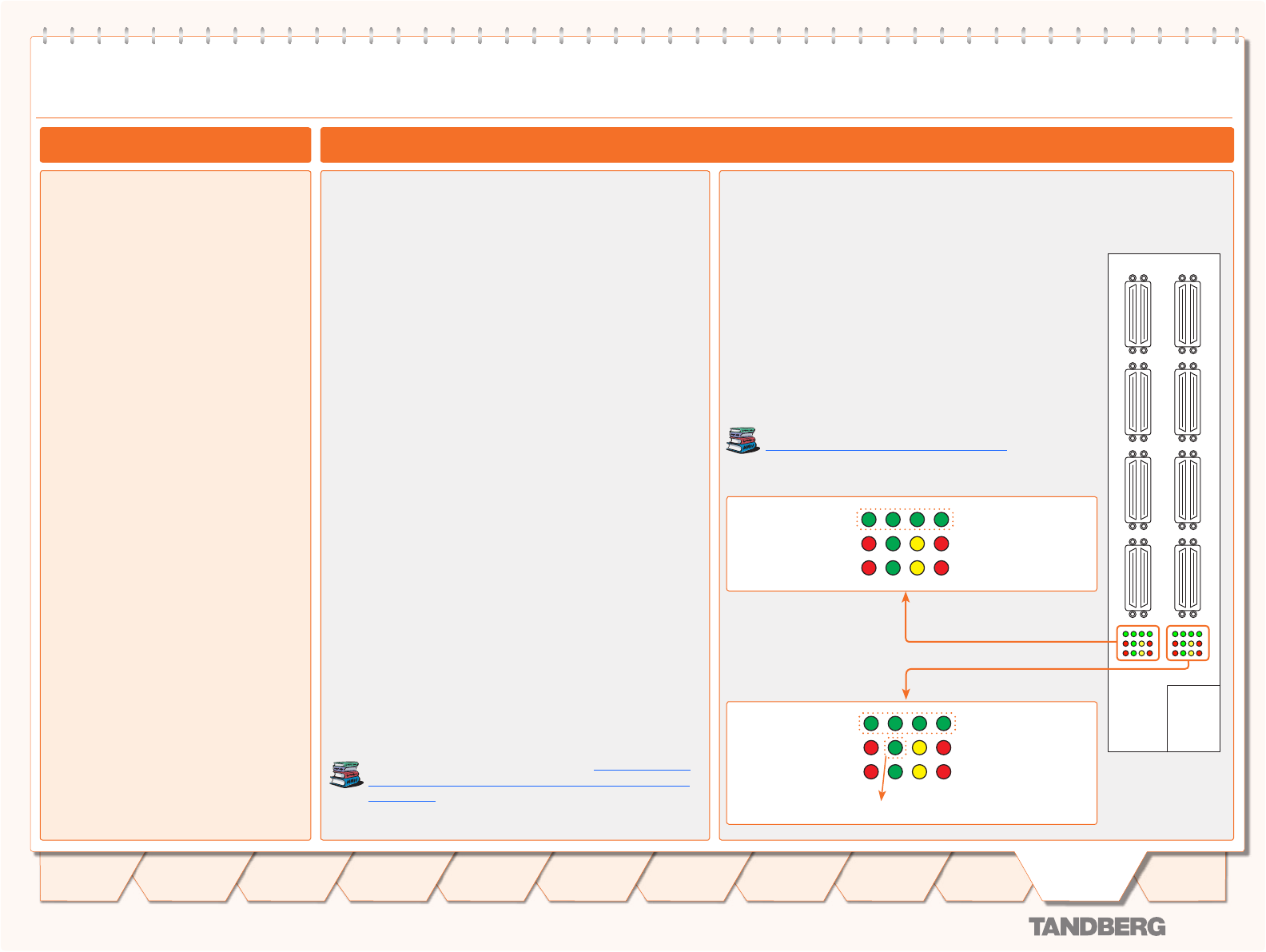
Chassis V.35 Serial Interface Card (SIC-32)
V.35 Serial Interface Card (SIC-32)
Network Interfaces
V.35 Serial Interface Card
32 x V.35 ports with optional RS366 Dialling•
Each port support rates from 64kbps up to 1920kbps•
Each port can either be dual-clocked (RS449, RS530, and •
V.35), or single clocked for X.21 applications.
V.35 ports/options are purchased in groups of 8 V.35 ports.•
Connecting the Card
A Media Processing Board must be in front of each V.35 Serial
Interface Card. See the TANDBERG MPS 800 V.35 interface
cards on how the V.35 Interface Cards are installed in the rear
of the chassis.
V.35 is shipped as a kit. The V.35 kit includes the following:
The V.35 Serial Interface Card•
4 cables that convert from high-density connectors on V.35 •
card to TANDBERGs standard V.35 connectors (26pin DSUB)
19” rack-mountable panel where the V.35 connectors will fit.•
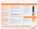
Light Emitting Diodes (LEDs)
You will also find Light Emitting Diodes (LEDs) on the board. The
LEDs gives you visual feedback on the status of the board.
Cable Specifications
To get more information on the cables needed to connect to the
26pin DSUB, refer to the following Cable Specification Docu-
ments:
V.35 Cable specification, D1231201•
V.35 and RS366 Cable specification, D1230501•
X.21 Cable specification, D1230101•
The above documents can be found on http://www.tand-
berg.com/support/documentation.php?p=Components_
and_Cables
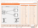
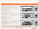
31-32 27-28 23-24 19-20
SIC-32
29-30 25-26 21-22 17-18
15-16 11-12 7-8 3-4
13-14 9-10 5-6 1-2
Rear View
The V.35 Card is equipped with V.35 ports for serial interface:
32 x V.35 ports with optional RS366 Dialling•
Light Emitting Diodes (LEDs) for V.35 Port status:
Green Blink• – The LED flashes every 2nd second to indi-
cate the driver on the board is OK.
Red Alarm• - The LED(s) turns red when an alarm appear on
any of the ports. Each LED indicates status of four ports.
Green Power/Restart• - The LEDs indicates the power sta-
tus. While in restart mode one LED will blink.
Yellow LEDs• - Always On
For more information about status on the V.35 card, see
System Status > Serial V.35 Board Status
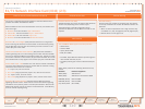
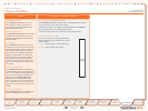
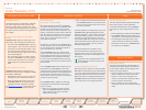
Red Alarm Port 1-4
Red Alarm Port 9-12
Red Alarm Port 5-8
Red Alarm Port 13-16
Green - Power/Restart
Red Alarm Port 17-20
Red Alarm Port 25-28
Red Alarm Port 21-24
Red Alarm Port 29-32
Green - Power/Restart
Green Blink - Board OK
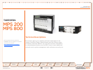
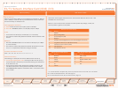
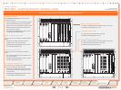
TANDBERG MPS 800
The TANDBERG MPS 800 has a 9U-19”
rack-mountable chassis that can host
up to 8 Media Processing Boards and 4
Network Interface Cards.
TANDBERG MPS 200
The TANDBERG MPS 200 has 3U-19” rack-
mountable chassis that can host up to 2
Media Processing Boards and 2 Network
Interface Cards.
Front Chassis
The TANDBERG MPS chassis is 19” rack-
mountable. On the front of the chassis is a
Liquid Crystal Display (LCD) for initial con-
figuration and basic system information.
You will also find 4 Light Emitting Diodes
(LEDs) for power status. The backplane
of the chassis is provided with advanced
CompactPCI technology for high speed
communication between the boards. You
will find 3 cooling fans in the lower front of
the chassis.
Rear Chassis MPS 800
The TANDBERG MPS 800 is shipped with
2 hot-swappable power units for configura-
tions of 1 to 3 Media Processing Boards. If
the unit has more than 3 Media Process-
ing Boards the TANDBERG MPS 800 is
equipped with 3 hot-swappable power
units. The power units are installed at the
back of the chassis. You will also find the
power switch/connector at the back of the
chassis.
Rear Chassis MPS 200
The TANDBERG MPS 200 is shipped with 1
power unit integrated in the chassis.
151
Introduction
Quick
Setup
Using
the MPS
System
Status
System
Configuration
Installation
Gateway
Configuration
MCU
Configuration
Appendices
Main
Technical
Descriptions