


D 13373.08
NOVEMBER 2007
MPS
Table of
Contents
TANDBERG MPS
ADMINISTRATOR GUIDE
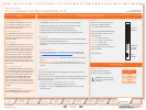
Chassis E1/T1 Network Interface Card (IIC-8)
E1/T1 Network Interface Card
The MPS 800 supports up to 4 E1/T1 Network Interface Cards. •
The MPS 200 supports up to 2 E1/T1 Network Interface Cards. •
Each E1/T1 Interface Card gives 8 E1/T1 PRI ports. •
PRI ports/options are purchased in groups of 4 PRI ports.•
The E1/T1 Interface Card is also used for G.703 Leased Line calls.•
ISDN Protocol
All 8 PRI ports on the same PRI card must use the same ISDN protocol •
and the same network interface (E1 or T1).
However, there is support for separate PRI protocols on each E1/T1 Inter-•
face Card.
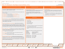
Connecting the Card
The E1/T1 Interface Card is installed in the rear of the chassis. See •
the TANDBERG MPS 800 – E1/T1 interface cards on how the card is
installed.
One • Media Processing Board must be in front of each E1/T1 Interface
Card.
The • Network Interface Card connects into the back of a Media Pro-
cessing Board by connecting to its J5-connector from the back of the
chassis.
Network Clock
The card connected to Media Processing Board #1 provides the primary
network clock for the unit.
When you have an E1/T1 Interface Card connected to this Media Processing
Board, the command line interface command reconfigures which PRI-port
this clock is taken from:
xConfiguration SystemClock Port <0,1-8>
The value • 0 is auto, meaning the first port with a clock.
The value • 1 - 8 tells the TANDBERG MPS to take the clock from that
specific PRI-port.
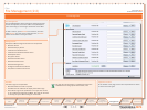
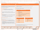
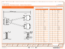
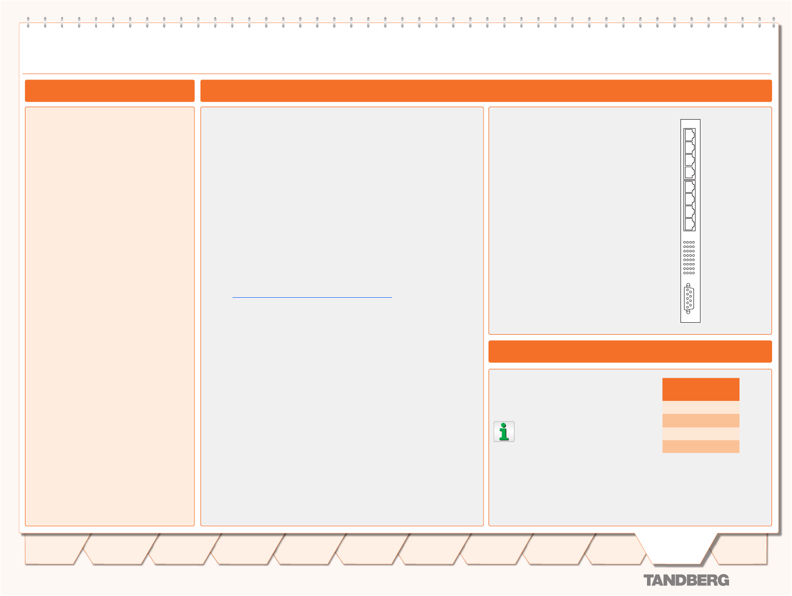
Rear View
The E1/T1 Card is equipped with
PRI ports for ISDN interface:
8 x E1/T1 PRI ports (RJ-45)•
Light Emitting Diodes (LEDs) for PRI
Port status, with 4 LEDs for each
E1/T1 PRI port:
Red• – Layer 1 Red Alarm
Yellow• – Layer 1 Yellow Alarm
Green• – Layer 1 OK
Red• – D-Channel Down
See next page for more information
about the LEDs.
Serial RS-232
PRI E1/T1 Cable
E1/T1 Network Interface Card (IIC-8) (1:3)
RS-232 8 7 6 5 4 3 2 1 8 7 6 5 4 3 2 1
8 x E1/T1
PRI Ports
4 LED’s for
each PRI
Interface
Serial
RS-232
PRI E1/T1 Cable
The cable of use should be a
straight through configuration.
TANDBERG recommends al-
ways using at least category
5 cabling.
PRI E1/T1 Pinout
PRI Pinout
1 TIP RX
2 RING RX
4 RING TX
5 TIP TX
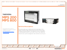
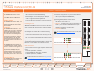
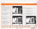
Network Interfaces
TANDBERG MPS 800
The TANDBERG MPS 800 has a 9U-19”
rack-mountable chassis that can host
up to 8 Media Processing Boards and 4
Network Interface Cards.
TANDBERG MPS 200
The TANDBERG MPS 200 has 3U-19” rack-
mountable chassis that can host up to 2
Media Processing Boards and 2 Network
Interface Cards.
Front Chassis
The TANDBERG MPS chassis is 19” rack-
mountable. On the front of the chassis is a
Liquid Crystal Display (LCD) for initial con-
figuration and basic system information.
You will also find 4 Light Emitting Diodes
(LEDs) for power status. The backplane
of the chassis is provided with advanced
CompactPCI technology for high speed
communication between the boards. You
will find 3 cooling fans in the lower front of
the chassis.
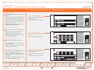
Rear Chassis MPS 800
The TANDBERG MPS 800 is shipped with
2 hot-swappable power units for configura-
tions of 1 to 3 Media Processing Boards. If
the unit has more than 3 Media Process-
ing Boards the TANDBERG MPS 800 is
equipped with 3 hot-swappable power
units. The power units are installed at the
back of the chassis. You will also find the
power switch/connector at the back of the
chassis.
Rear Chassis MPS 200
The TANDBERG MPS 200 is shipped with 1
power unit integrated in the chassis.
148
Introduction
Quick
Setup
Using
the MPS
System
Status
System
Configuration
Installation
Gateway
Configuration
MCU
Configuration
Appendices
Main
Technical
Descriptions