


D 13373.08
NOVEMBER 2007
MPS
Table of
Contents
Installation
TANDBERG MPS
ADMINISTRATOR GUIDE
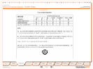
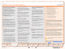
Precautions
Unpacking
To avoid damage to the unit during transportation, the TANDBERG MPS is
delivered in a special shipping box.
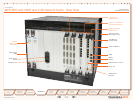
The shipping box contains the following components:
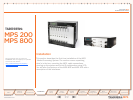
Chassis:1.
MPS 200, a 3U chassis with power supply.a.
or MPS 800, a 9U chassis with 2 or 3 x Power Units (depending on b.
the number of Media Processing Boards installed)
1 x System Controller Boardc.
The Media Processing Boards orderedd.
PRI E1/T1 ISDN Interface Card (if ordered)e.
V.35 Serial Interface Card (if ordered)f.
Administrator Guide and other documentation on CD2.
Installation sheets3.
4 screws and 4 nuts for rack mounting and 4 pads4.
Cables:5.
Power cablea.
Ethernet cablesb.
ISDN cables (optional)c.
V.35 kit (optional). The kit includes cables that convert from high-d.
density connectors on V.35 card to TANDBERG’s standard V.35
connectors (26pin DSUB) and 19” rack-mountable panel where the
V.35 connectors will fit.
RJ45 to RS-232 converter cablee.
What is in the Box?
Please read carefully:
Never install communication equipment dur-•
ing a lightning storm.
Never install jacks for communication •
cables in wet locations unless the jack is
specifically designed for wet locations.
Never touch uninstalled communication •
wires or terminals unless the communication
line has been disconnected at the network
interface.
Use caution when installing or modifying com-•
munication lines.
Avoid using communication equipment (other •
than a cordless type) during an electrical
storm. There may be a remote risk of electri-
cal shock from lightning.
Do not use communication equipment to •
report a gas leak in the vicinity of the leak.
The socket outlet shall be installed near the •
equipment and shall be easily accessible.
Never install cables without first switching •
the power OFF.
This product complies with directives: LVD •
73/23/EC and EMC 89/366/EEC.
Caution - Double pole fusing.•
Power must be switched off before power •
supplies can be removed from or installed
into the unit.
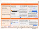
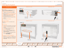
Mounting the MPS on a Rack
The TANDBERG MPS comes with 4 screws and 4 nuts for mounting in
standard 19” racks. The chassis is equipped with brackets.
Before starting the rack mounting, please make sure the TAND-1.
BERG MPS is placed securely on a hard, flat surface.
Disconnect the AC power cable.2.
Make sure that the mounting space is according to the 3. Prepara-
tions on Site in the section above.
Insert the chassis into a 19” rack, and secure with screws in the 4.
front (four screws) and nuts (four nuts).
Rack Mounting
Preparations on Site
The mounting space must be prepared before you start:
Make sure the TANDBERG MPS is accessible and that all cables •
can be easily connected
For ventilation: Leave a space of at least 10cm (4 inches) behind •
the TANDBERG MPS’s rear panel and 10cm (4 inches) in front of
the front panel
The room in which you install the TANDBERG MPS should have an •
ambient temperature between 0ºC and 35ºC (32ºF and 95ºF) and
between 10% and 90% non-condensing relative humidity
Do not place heavy objects directly on top of the TANDBERG MPS•
Do not place hot objects directly on top, or directly beneath the •
TANDBERG MPS
Use a grounded AC power outlet for the TANDBERG MPS.•
Precautions, Unpacking and Mounting
20
Introduction
Quick
Setup
Using
the MPS
System
Status
System
Configuration
Gateway
Configuration
MCU
Configuration
Technical
Descriptions
Appendices
Main
Installation