


D 13373.08
NOVEMBER 2007
MPS
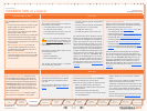
Table of
Contents
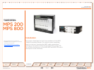
TANDBERG MPS
ADMINISTRATOR GUIDE
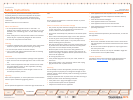
Introduction
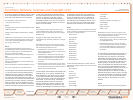
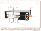
Rack Mountable Chassis Front View
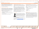
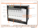
System Controller Board
The System Controller Board is installed in
the first slot in the chassis.
In the MPS 800 the first slot is the first •
from the left of the chassis.
In the MPS 200 the first slot is the first •
from the bottom of the chassis.
It is very important that the System
Controller Board is installed in the
first slot in the chassis! Installing in
any other slot can damage the System Con-
troller Board.
The System Controller Board takes care of
the following functions:
Call control•
System management•
The embedded Web server•
The System Controller Board is equipped
with the following interfaces:
1 X LAN / Ethernet (RJ-45) 10/100 Mbit •
on the front.
2 X LAN / Ethernet (RJ-45) 10/100 Mbit •
on the back (only 1 in use, Enet2)
1 x COM port on the front•
2 X USB port (these are for future use)•
The LAN interface on the System Controller
Board is for management/call control signal-
ling. Note that management is disabled on
Enet2. This interface is only for call control.
The 2 LAN interfaces will allow you to con-
nect to two non-overlapping IP-networks so
that participants with no IP-routing between
them can be joined in the same conference.
At least one Media Processing Board must
be connected to each network. The 2xLAN
interfaces will give the TANDBERG MPS
support for two Gatekeepers, one on each
network. To use the COM1 port you need a
RJ-45 to RS-232 converter. See the Techni-
cal Description section for further details of
the COM port pin out on the System Control-
ler Board.
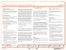
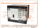
Network Interface Cards
The Network Interface Cards of the TANDBERG
MPS are installed from the rear panel.
There are two types of Network Interface Cards:
PRI E1/T1 ISDN Interface Card (IIC-8). •
Each PRI E1/T1 ISDN Interface Card has 8 x
PRI interfaces.
V.35 Serial Interface Card (SIC-32). •
Each of the V.35 Serial Interface Card has 32
x V.35/RS366 ports.
There is support for up to 4 Network Interface
Cards.
There can be a mix of PRI E1/T1 ISDN Interface
Cards and V.35 Serial Interface Cards.
The PRI E1/T1 ISDN Interface Card and the V.35
Serial Interface Card may only be installed in slot
1-6. (1 being the first Media Processing Board,
left from the System Controller Card, seen from
the rear).
See the Technical Description section for further
details of the different Network Interface Cards.
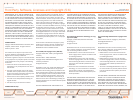
The TANDBERG MPS chassis is 19” rack-mount-
able.
On the front of the chassis is a Liquid Crystal •
Display (LCD) for initial configuration and
basic system information.
There are four Light Emitting Diodes (LEDs) •
indicating the power status.
The backplane of the chassis is provided with •
advanced CompactPCI technology for high
speed communication between the boards.
There are three cooling fans in the lower front •
of the chassis.
The • TANDBERG MPS 800 has a 9U-19”
rack-mountable chassis that can host up
to 8 Media Processing Boards and up to 4
Network Interface Cards.
The • TANDBERG MPS 200 has 3U-19” rack-
mountable chassis that can host up to 2 Me-
dia Processing Boards and up to 2 Network
Interface Cards.
Media Processing Board
Add-on boards for media processing are installed in
adjacent slots in the chassis. The Media Processing
Boards handles the following functions:
Video processing. See • Video Features in the Tech-
nical Descriptions section for details.
Audio processing. See • Audio > Create Conference
in the Using the MPS section for details.
Transcoding. See • Transcoding and Ratematching in
the Technical Descriptions section for details.
Encryption. See • Secure Conference (Encryption) in
the Technical Descriptions section for details.
Continuous Presence/Voice Switching. See • Video
Features in the Technical Descriptions section for
details.
Each of the Media Processing Boards is equipped
with 1xLAN interface for H.323 and SIP media. You
will also find 4 Light Emitting Diodes (LEDs) for board
status. With the TANDBERG MPS 800, there is sup-
port for up to 8 Media Processing Boards. With the
TANDBERG MPS 200, there is support for up to 2
Media Processing Boards. See the Technical Descrip-
tion section for further details on the Media Process-
ing Board.
!
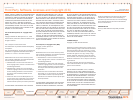
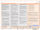
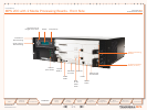
Rear View
System Controller Board - Rear View
The second LAN interface of the System
Controller Board is accessible from the
rear side.
See the Technical Description section for
further details on the System Controller
Board.
TANDBERG MPS at a Glance
The TANDBERG MPS 800 is shipped with 2
hot-swappable power units for configurations
of 1 to 3 Media Processing Boards. If the unit
has more than 3 Media Processing Boards the
TANDBERG MPS 800 has to be equipped with
3 hot-swappable power units. The power units
are installed at the back of the chassis. You
will also find the power switch/connector at the
back of the chassis.
The TANDBERG MPS 200 is always shipped
with 1 power unit integrated in the chassis.
18
Quick
Setup
Using
the MPS
System
Status
System
Configuration
Installation
Gateway
Configuration
MCU
Configuration
Technical
Descriptions
Appendices
Main
Introduction