


D 13373.08
NOVEMBER 2007
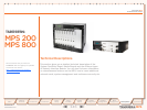
MPS
Table of
Contents
TANDBERG MPS
ADMINISTRATOR GUIDE
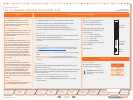
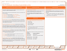
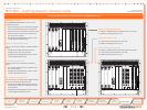
You will find 4 Light Emitting Diodes (LEDs) for each PRI interface which
provides information about PRI-line status.
Read the LEDs for each of the PRI interfaces on the E1/T1 Interface Card
from left to right:
Red LED1. - If On this indicates Layer 1 Red Alarm
Yellow LED2. - If On this indicates Layer 1 Yellow Alarm
Green LED3. - If On this indicates Layer 1 OK
Red LED4. - If On this indicates that D-channel is Down
Red Alarm or Loss of Signal (LOS) indicates that there is no signal and
thus no framing info received. The same effect will be obtained by pulling
out the PRI cable. This may also be caused by a broken connector in the
receive (RX) part of the cable.
Yellow Alarm or Remote Alarm Indicator (RAI) means that the MCU is
receiving framing info, but in this framing info the other side tells the MCU
that it is not reading the MCU’s transmitted framing info. Typically, this may
be a broken connector in the transmit (TX) part of the PRI cable. This could
also indicate weak or noisy signal in the transmit (TX) part of the PRI cable.
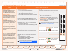
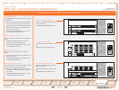
Green LED or Layer 1 OK doubles as a clock source indicator. The LED for
one of the eight interfaces will flash to indicate that the interface is being
used as the clock source for H.110 bus.
On• - Layer 1 OK, not clock source
On + Flash• (long On/short Off) Layer 1 OK, used as clock source
Off• - Layer 1 Down, not clock source
Off + Flash• (long Off/short On) Layer 1 down, used as clock source
Red Alarm or D-Channel Down indicates that the ISDN out-of-band
signalling channel is down. The D channel carries user-network signalling
information and is primarily used in call setup and teardown. Note that for
NFAS the D channel may not be used for all PRI interfaces. A red LED may
thus not indicate anything wrong.
E1/T1 Network Interface Card (IIC-8) (2:3)
LED’s for the E1/T1 PRI Interface Card (IIC-8) Channel Service Unit
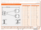
Channel Service Unit (CSU)
The PRI interface may require an external CSU (Channel
Service Unit) depending on the network layout.
The Cable Length in the PRI configuration menu
specifies the distance from the MCU to the CSU or last
repeater.
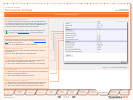
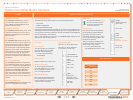
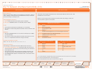
PRI Protocols
The TANDBERG MPS supports the PRI protocols
AT&T Custom•
National ISDN•
Japan/Taiwan ISDN•
ETSI (Euro ISDN)•
The AT&T, Japan ISDN and National protocols gives a •
total of 23 B-channels per port
The ETSI protocol gives a total of 30 B-channels per •
port.
Within these protocols the following switches are sup-
ported:
Switches Protocolssupported
4ESS (AT&T) AT&T Custom
5ESS (AT&T) AT&T Custom and National ISDN
DMS250 (Nortel) National ISDN
DMS100 (Nortel) National ISDN
(Any switch) ETSI (Euro ISDN)
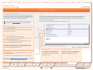
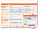
Channel Hunting
Channel Hunting
Channel hunting is provided for outgoing calls. The feature
is normally used when the number of channels needs to be
specified.
When no value is specified for low or high channel, they •
are default to 1 (low), 23 (high US) and 30 (high Europe).
Default search is from high to low.•
Network Interfaces
149
Introduction
Quick
Setup
Using
the MPS
System
Status
System
Configuration
Installation
Gateway
Configuration
MCU
Configuration
Appendices
Main
Technical
Descriptions